Eng-Tips is the largest engineering community on the Internet

Intelligent Work Forums for Engineering Professionals

Flow Coefficient calculation of Choke Valves 1

Status
Not open for further replies.

Ahsan96

Mechanical
Mar 3, 2024
7
0
0
BH
Hi Members,

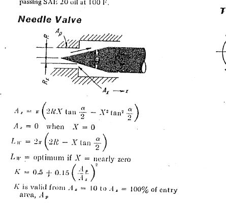
I have just started working on control valves such as Choke Valves, the typical needle and stem type. Now I am looking for reading material or general calculations I can use to calculate Pressure loss and Cv Value theoretically for choke valves, which I can later verify through actual experiments.

Regards,
AAI
 
Replies continue below

Recommended for you

Almost certainly such information is only available via flow curves and other performance information from the valve makers.
 

Thanks for the quick response, you are right. But there are ways to calculate friction "K Factor" using equivalent Lengths. Then use the head loss/darcy–Weisbach equation to get the pressure loss.

 
A choke valve is basically a valve that restrict the flow at a given dP - and is operating in the "sonic velocity" range so that the flow is limited by the square root of the dP. So max. capacity at full open is interesting, but all positions in between is not that interesting.

Consider a choke valve at a gas or oil well. Downstream the choke valve the pressure is determined by the control valve/compressor in the separator.

The valve position is chosen to restrict the flow rate so that the down stream system can cope.

And i agree with 3DDave, get the curve from the supplier.

--- Best regards, Morten Andersen
 
Trying this forum for the first time, really appreciate the quick response from you guys.

I believe it is my poor choice of words that led to this confusion. This is not something that is being supplied, I am working on product development of "Needle and seat choke", the end-user has the requirement to get the "flow curve" which they can use to throttle the flow by adjusting the equivalent orifice size by using the handwheel and the visual indicator.

I am looking for reading material to have a bit more understanding of calculating friction factors, which can later be used to calculate Cv (flow coefficient) at a particular flow rate & orifice size.
 
It is so sensitive to geometry that I cannot imagine a formula would be developed to cover all possibilities. If there was, the valve makers would not do the flow testing to produce the flow curves.

How much flow, what material is being controlled, what pressure, what pressure drop ...?
 
Second, you 3DDave.

However, there was some reference I was able to pull out to give me a rough estimate of resistance "K" that would be similar to "needle and seat case" I am working on.

1_mhqzqe.jpg


Using the K calculated (for a specific Orifice size) from here to give me a Headloss/Pressure loss using Darcy–Weisbach, which could give me a rough Cv value (at an assumed Average velocity) which would then be validated using flow testing.

How legit would you say this process would be

The picture is extracted from "LYONS' VALVE DESIGNER'S HANDBOOK"
 
Status
Not open for further replies.
Back
Top