Continue to Site

Eng-Tips is the largest engineering community on the Internet

Intelligent Work Forums for Engineering Professionals

  • Congratulations KootK on being selected by the Eng-Tips community for having the most helpful posts in the forums last week. Way to Go!

Flow rate change in centrifugal pump without changing impeller size or motor power or motor speed 5

Status
Not open for further replies.

Nick47

Mining
Jan 7, 2016
14
Hello,
There is centrifugal pump with constant speed (no VFD), as per pump curve it can provide different flow rate which will cause to have different DH.
How would it be possible to have higher/ lower flow rate from the pump without changing the impeller size, motor speed, and no change in suction and discharge line?
Thanks for your advise.
 
Replies continue below

Recommended for you

Flow rate from centrifugal pumps depends on the system curve. Any changes upstream or downstream will affect the flow rate.

As the pump wears performance in general is going to degrade.

Between two new pumps, clearances affect overall performance.
 
By restricting the fluid going to, or attempting to exit, the pump, ie. with a valve or by other means.

With no change in any of the variables you mention, there would be no change in flow. If you change the flow in the suction or discharge lines, by closing a valve, or reducing pump speed, or whatever, then you would obviously get a change in pump flow and the knock on effect is a change in the differential pressure it produces. Likewise, a change in pressure, by opening/closing a valve or whatever also has knock on effect on flow. I say knock on effect to emphasise the different result, however the change happens simultaneously, not as a true knock on effect would, one after the other. Pressure and flow always vary together and cannot be separated into one causing the other, although the results are often thought of in that manner. Pressure and flow variations happen simultaneously over any given time step. Hope that isn't confusing the issue, if it is, think about that later.

The pump's curve describes the pump's ability to share its total input power between output of flow verses pressure. For a fluid with unit density, 1/(flow[sup]n[/sup]) x head = power. n varies with the flow rate of fluid allowed to pass through the pump. n is related to friction and the pump's efficiency. Thus if flow is low, pressure differential will be large. If flow is high, pressure differential will be low.

A change in any one, or more, of the mentioned variables will cause changes in others such that the pump curve always describes the resulting share of the pump's input power going towards producing both flow or head. The more power going to producing differential head, there is less power available to produce flow. The more power going to producing flow, there is less power available to produce differential head.

--Einstein gave the same test to students every year. When asked why he would do something like that, "Because the answers had changed."
 
Although a centrifugal pump has a range where it is most efficient, it will work almost anywhere along its curve. Restriction on the suction side is not a good idea, and care must be taken to not work the pump at either the extreme right or left side of the curve. But many pumps will work fine well below the published minimum safe continuous flow rate. Many people think a VFD is needed to reduce energy consumption, however the power required for a centrifugal pump naturally decreases with a restriction of discharge flow without varying the speed. A VFD or a pump control valve can be used to control or maintain constant pressure. In many cases there is very little difference in energy consumption of a full speed pump controlled by a valve and varying the pump speed with a VFD.
 
Nick47 said:
How would it be possible to have higher/ lower flow rate from the pump without changing the impeller size, motor speed, and no change in suction and discharge line?

I'm not sure if this is philosophical question or if you have a particular issue in mind?

The short answer is that unless you change something the flow rate won't change.

You either increase the pressure in the pump inlet which then results in higher pump outlet pressure to get higher flow or you somehow add more frictional losses or add static head to the outlet system to get lower flow. So e.g. if you are filling a tank and nothing else changes other than tank level the flow will be lower as the tank fills up. How much lower depends on how much head the pump is producing and how much of the total head loss is friction and how much is the increasing static head.

Oh I forgot - If you change the pumped fluid SG and viscosity then the flowrate and power used will change..

Remember - More details = better answers
Also: If you get a response it's polite to respond to it.
 
it's well covered above but just to contrast vfd/speed changes vs system changes (for op):
[ul]
[li]vfd changes the entire pump hd vs flow curve.[/li]
[li]at a given speed there is still a curve. The operating point is intersection of pump curve and system curve. changes in system curve will affect where on the pump curve the operating point is[/li]
[/ul]
 
@Valvecrazy:
I have a question on your statement that “Many people think a VFD is needed to reduce energy consumption, … In many cases there is very little difference in energy consumption of a full speed pump controlled by a valve and varying the pump speed with a VFD”
Is your statement fair when this simple math is applied? just see the following example with unchanging total efficacy (64% for this purpose), in which the first condition is 1500 gpm, the needed flow rate is 1200 gpm, and the 300 gpm is to be decreased by throttling or regulating flow.
The first condition
Flow rate= 1500 gpm
Head = 80ft
Power=1500*80/ (5308*64%) =35KW

[highlight #FCE94F]With throttling flow (head increases when throttling)
Flow rate= 1200 gpm
Head = 90ft
Power=1200*90/(5308*64%)=32KW[/highlight]
With varying flow by VFD (head decreases when varying along with flow rate)
Flow rate= 1200 gpm
Head = 60ft
Power=1200*60/ (5308*64%) =21KW

Throttling yields more power (32-21 = 11 kw) than changing flow.


The problem with the world is that intelligent people are full of doubts, while stupid ones are full of confidence.
-Charles Bukowski-
 
Each situation is different.

Depends on your system curve and how efficiency changes with speed.

Also don't forget the losses in the VFD, about 8 to 10%. And the CAPEX and space and heat from the VFD.

And how often is the low flow needed.

With only a small change, 65ft and 0.62, plus the vfd, you get to 26kW.

If the head rise is only 86ft you get 30 kW.

Or buy a smaller pump or trim the impellor if this condition is permanent.

Remember - More details = better answers
Also: If you get a response it's polite to respond to it.
 
If your pump curve is flatter there is also far less difference in power when throttling.
Your example pump loses 33% head with a 20% increase in flow. That's a relatively steep pump curve, which might imply that the example pump is undersized for operation at 1500gpm.

You also assume that a 90ft head is reached when throttling to 80% flow, indicating that BEP head is somewhat less than the 90ft, maybe 80 or 75ft?, yet I think you used 90ft, x 0.8^2 = 60ft as your vfd produced head. It would probably be more like 70 to 80ft x 0,8^2, or around 45 to 50ft head available, not 60, so that would be around 60% of head needed at 1500gpm. A 100-45/75 = 40% loss of head with a 20% reduction in pump speed. The question that makes the difference is, will your system curve flow 80% at 60% head? Id bet it needs more.


--Einstein gave the same test to students every year. When asked why he would do something like that, "Because the answers had changed."
 
Just something to consider.


reference “Centrifugal and Axial Flow Pumps” (a book by A.F. Stepanoff, John Wiley publication, 2nd Edition, page 293).

In this book, Stepanoff defines the conditions needed for the curve to be unstable:

The mass of water must be free to oscillate, a typical scenario in boiler feed applications.
There must be a member in the system that can store and give back the pressure energy or act as a spring in a water system. In a boiler feed pump cycle, the elastic steam cushion in the boiler also serves the same purpose. Long piping can also do the same.
 
The value of the head variation was calculated using an approximation. While applying the affinity law with 1480 motor RPM in first condition, 1184 rpm is needed to reduce the flow from 1500 gpm to 1200 gpm. The head will drop from 80 to (1184/1480) ^2*80=51 FT/HD
When the 8% vfd drive loss is taken into account, the efficiency drops from 64 to 59%, but the vfd operation outperforms throttling. 1200*51/(5308*59%) =19.7 KW. I agree with the calculation's correctness because I cannot precisely determine the head fluctuation of the throttling procedure.


The problem with the world is that intelligent people are full of doubts, while stupid ones are full of confidence.
-Charles Bukowski-
 
A better pump selection would negate most, or all of any savings. It needs to operate on a flatter curve where head increase on flow reduction is not so pronounced.

--Einstein gave the same test to students every year. When asked why he would do something like that, "Because the answers had changed."
 
Hi,
Any feedback from the OP? This is ridiculous. We should not waste our time.
Pierre
 
Thank you all for the responses, so I believe we can manage flow rate and head by throttling discharge valve an achieve to the different flow rate/ head as per pump's curve.
 
Sorry, I should have said "while maintaining the same head" there is very little difference in energy consumption comparing a VFD to a throttling valve. As was also said, a pump with a more flat curve makes VFD control even less advantageous.
 
Most rated conditions do seem to be towards the flatter parts of the pump curves, because that's where efficiency is normally the highest, then falls off quickly just afterwards. Poor efficiency at high flow rates means high operating costs too. Generally you shouldn't be out that far on the curve, but there are some cheap power hogs out there. VFDs more commonly competitive at a 30% or more flow reduction for sustained periods ( 40% of the total operation time.).

--Einstein gave the same test to students every year. When asked why he would do something like that, "Because the answers had changed."
 
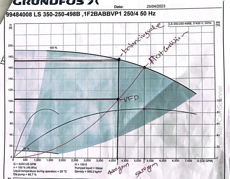
Okay, I'm going to do an experiment with a flat curve and a reduction of 20% to 40%. For experiments, I use a flat curve; the subjected secondary chilled water pump is currently powering my facility. I am corresponding the curve to the first condition, which is 5250 gpm at 159 ft/hd at 1490 rpm. The efficiency of wire-to-water is 77%. The kw is then (5250*159)/(5308*77) = 205 kw.

Planning to reduce flow rate by 20%, so it will be 4200 gpm; adjusting the balancing valve to reduce flow to 4200 gpm; increasing head to 172 ft/hd; and dropping efficiency to 2%.then the power will be 4200*172/(5308*75)=181.5kw.
with VFD of 8% drive loss, the head dropped to 101.7ft
the power will be 4200*101.7(5308*71%)=113.7 kw
the difference is=181.5-113.7=68 kw, a considerable shift, even a 20% reduction in flow
curve-vfd_vs_drv_jlawme.jpg


The problem with the world is that intelligent people are full of doubts, while stupid ones are full of confidence.
-Charles Bukowski-
 
es, OK. The pump curve is flatter, so there is less gain of head when flow is reduced. A real improvement. Problem #1 solved. However now that the pump curve problem has been solved, We can see and solve the real problem with this system. The system curve is also very steep. If it gives you such a large difference in head (and power consumption) between 80 to 100% flow, the pipe diameter is definetely too small. That's a 70% something increase in power for a 20% increase in flow. IMO, that's way too high. It should be more like 40 to 50% max. The system curve should never have been designed to require so much power at any flow rate. Such high operating costs would typically be reduced with larger piping requiring less head overall. I have seen these designs used a lot in countries that have very low power costs. If power costs rise, it will not be economic to run the system at 100% flow in any case and a VFD can be a good solution to reduce power consumption at 80% flow. Many vfds have found to be of use in "fixing" what should have been a better, more optimized, design, like what happens after everyone adds their 10% fudge factors.

--Einstein gave the same test to students every year. When asked why he would do something like that, "Because the answers had changed."
 
There should have been horsepower on that curve, which would have saved you from doing the math or making any mistakes. Because it looks to me like like at 4200 GPM that pump is still 82% efficient not 2%. It is 2% efficient at like 100 GPM.
 
Too many possible options here. Many system curves have an element of static head (elevation difference, pumping into a tank, high point on the pipeline etc.

This flattens the system curve and also means lower flow heads higher pressure than your assumption of head being directly proportional to flow^2.

Every system is different so some will be suited to VFDs, others won't. That's all anyone is trying to say. Change a few assumption on your example and suddenly there is very little or no cost saving or power saving.

Also pumps change efficiency as speed changes. Some static elements increase as a percent of frictional losses so it's not easy to say what the efficiency is at a different speed.

Remember - More details = better answers
Also: If you get a response it's polite to respond to it.
 
Status
Not open for further replies.

Part and Inventory Search

Sponsor