Eng-Tips is the largest engineering community on the Internet

Intelligent Work Forums for Engineering Professionals

Flow rate not fulfilled in revamped recip compressor 1

Status
Not open for further replies.

pyMorty

Industrial
Mar 9, 2014
46
0
0
MX
We just revamped two identical reciprocating compressors, from 3 stages high pressure to a low pressure sigle stage, in order meet the following:

Required Operating conditions:

Suction: 25-40 psig
Discharge: 120 psig
Flow (calculated with compressor brand software [CiP]): 2.4 (25 psig suction) - 4.0 MMSCFD (40 psig suction)

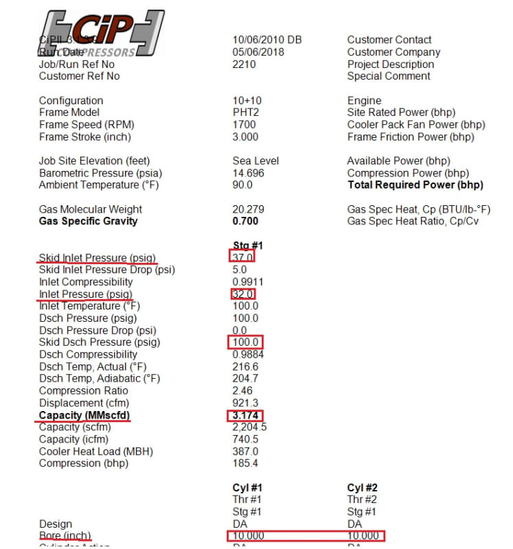
Two identical units were revamped, original frame CiP PHT-2 and CAT G3406TA were kept, replacing cylinders to go from 3 stg to a single stage unit, with two new 10" cylinders.

Current operating conditions:

Suction: 37 psig
Discharge: 100 psig
Flow measured with orifice plate and Nuflo Scanner 2000: 2.0 MMSCFD

With that suction pressure we should be getting at least 3.2 MMSCFD (volume pockets closed all the way, 1700 RPM. We are 1.2 MMSCFD short comparing the calculation from the software and the reality on site.

According to this conditions we should have a driver percent load of 66 %, therefore no engine overloading should be expected

Since the same thing is happening in both of the units we are considering the following:

1. Undersized scrubber. I made the calculations again and the scrubber is actually undersized, it is good for just about 3.0 MMSCFD @40 psig. However this should just affect the liquid separation efficiency, not the flow rate

2. Undersized piping: Cylinders flanges are 6", whereas suction piping is 4". This should just increase velocity and cause a dP from skid inlet to cylinder nozzle. This dP has been measured as 5 psig. We are still having enough pressure getting into the cylinders to get more flow, but still not meeting the flow.

3. Piping arrangement, as shown in the General Arrangement drawing below, the suction piping is not centered between the two cylinders, but just to one of them, however both cylinders have fixed capacity at certain pressure, so the flow should keep near to the same in both of them.


Compressor_Miq_atcl9u.jpg


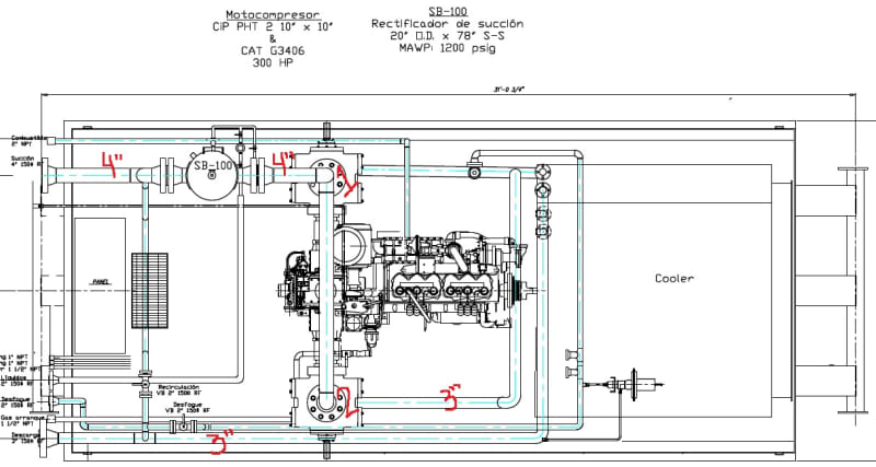
The performance run was reviewed by the compressor manufacturer, so the difference in flow rate has to be caused by something done during the revamp.

What is weird to me is that the suction pressure is not droping, meaning the cylinders are being filled, if they were not getting enough gas pressure this would drop until they are filled with the available source. We are having some compression valves high temperature, though.

What do you think the possible cause could be?

Performance run showing the expected flow rate:

Comp_performance_up2ge6.jpg


I hope the information I provided is enough for you to analice and share your thoughts. Please let me know if I missed something else you need.

I appreciate your comments.
 
Replies continue below

Recommended for you

For this kind of problem, there are 3 questions that you HAVE to be able to answer before you can start your analysis:
[ol 1]
[li]Where are the suction/discharge pressure/temperature taken? If it is not within a few feet of the cylinder suction valves then you are wasting your time[/li]
[li]Is there anything that could be effecting your flow rate indication (e.g., I once spent a week chasing a similar problem and finally in desperation I inspected the orifice plate and found it installed backwards which gave us a 36% low reading and showed that the compressor was perfect)?[/li]
[li]Finally, have you, yourself run the Ariel Performance model for the actual measured conditions? You don't talk about temperatures in your post, it is crucial to compare Ariel's predicted discharge temperature for actual input temp to measured discharge temperature--if they don't match within 1-2°F then you have a problem (most often if the measured temp is high then your suction valves are too stiff and opening late, if the measured temp is too low then you likely have a leaking suction valve). Computer models never prove anything, but the good ones (and Ariel Performance is one of the best) can certainly point to interesting areas to investigate.[/li]
[/ol]

[bold]David Simpson, PE[/bold]
MuleShoe Engineering

In questions of science, the authority of a thousand is not worth the humble reasoning of a single individual. Galileo Galilei, Italian Physicist
 
Thank you zdas04.

Regarding your questions:


1. Where are the suction/discharge pressure/temperature taken? If it is not within a few feet of the cylinder suction valves then you are wasting your time
-They are being taken from sensors located right in the cylinders, and also in the scrubber and discharge lines. I´m requesting lastest readings to put them in the performance runs.

2. Is there anything that could be effecting your flow rate indication (e.g., I once spent a week chasing a similar problem and finally in desperation I inspected the orifice plate and found it installed backwards which gave us a 36% low reading and showed that the compressor was perfect)?

-Maybe. I checked the beta of the orifice plate (manufactured on site for the local contractor of the mechanical work) exceeds standard range (0.15 to 0.67). The beta of the installed one is 0.70, also it has no bevel...


3. Finally, have you, yourself run the Ariel Performance model for the actual measured conditions? You don't talk about temperatures in your post, it is crucial to compare Ariel's predicted discharge temperature for actual input temp to measured discharge temperature--if they don't match within 1-2°F then you have a problem (most often if the measured temp is high then your suction valves are too stiff and opening late, if the measured temp is too low then you likely have a leaking suction valve). Computer models never prove anything, but the good ones (and Ariel Performance is one of the best) can certainly point to interesting areas to investigate.

-The performance run software I´m using in this case is the one provided by the compressor brand the cylinders are for, CiP (Cylinders in Plane). I´m checking with Ariel trying to costumize the cylinders (Ariel has 10.5", whereas the ones installed are 10.0", also I´m putting the same clearance). I´m getting 2.7 MMSCFD in Ariel, with same bore cylinder, whereas in CiP I get 3.1 MMSCFD, same conditions put in.


Given your comments you are kind of ruling out the problem being pipe arrangement (not being centered to the cylinders), pipeline size, and scrubber sizing?

Am I right stating that since the suction pressure is not droping down it means the cylinders are being filled? meaning there could be loses or measurement discrepancies?

Also crew on site have noticed engines heating up, weird since even handling all the flow the software calculates 67 % power utilization.

 
Have you verified the 32°F point on the temp sensors? The zero on the pressure sensors? If either is very far off then it is necessary to do a full-blown calibration.

A 6-inch orifice meter without a bevel increases uncertainty about 12% (with a strong bias towards reading low). 0.7 Beta ratio probably gives you another 4-5% increase in uncertainty--if the tube is not built to ASME 14.3 then you likely don't know the roughness of the pipe nor are you likely to be controlling the flow profile. The tube could easily be +5 to -20% of the output reading. Do you have any system-balance information to give you a feel for the actual value (sometimes if the sum of the inputs is close enough to the combined output you can ignore differences in individual meters). Without reliable flow, temperature, and pressure numbers, the rest of the troubleshooting is a waste of time.

I haven't the run NGSG program, I've worked around their compressors a bit, but not enough to form an opinion on them. On your CIP run if the "actual" is actually actual, then that 12°F difference should have set off red flags in the analysis, if it is just a plug value (like it often is for a sizing run, and the 100.0°F suction temperature makes me think it probably is) then get real data and re-run it. The CIP program might be fine, but I don't know.

My list is the things I check before I start really looking hard. Satisfying that short list simply puts you in a position of using the data instead of questioning the data. If the actual data from the suction plenum to the discharge plenum matches a program that you believe, then your problem is outside of the compressor and it is right to begin looking at pipe and equipment sizing and pressure drops,

[bold]David Simpson, PE[/bold]
MuleShoe Engineering

In questions of science, the authority of a thousand is not worth the humble reasoning of a single individual. Galileo Galilei, Italian Physicist
 
a) If the orifice plate was meant to operate at 40psig, and its now at 37psig or lower at the location of the orifice plate, did you enable pressure compensation correction on the flow ?
b) Some of the valves are heating up ? These valves may be leaking, or you may have broken piston rings? What is the actual discharge temp from these 2 cylinders, an how does it compare to the predicted ?
c) Discharge to suction recycle control valve leaking ?
 
georgeverghese,
From the gas specific gravity, I would say with some certainty that we are not talking about an air compressor, and I have never seen orifice measurement station for flow measurement of industrial gases that was not using the ASME 14.3 calculations, which of course are pressure compensated.

[bold]David Simpson, PE[/bold]
MuleShoe Engineering

In questions of science, the authority of a thousand is not worth the humble reasoning of a single individual. Galileo Galilei, Italian Physicist
 
Where do you read the flowrate and other instruments indication, is it on a control panel or some sort of HMI monitoring system in the control room ?

I ask this question because I would expect that after compressor is upgraded, you would normally have to upgrade the control system. Where I am heading at is the flow measurement device calculations. For instance the calibration ranges of the instruments normally need to be updated based on your operating envelop / processed gas. Normally there is also some fixed coefficient that transform actual flow to mass flow or MMSCFD that display in the monitoring system . Has this been checked by OEM or whovever did the upgrade?

 
rotw, that is exactly what I was talking about--you have to make certain that your data is accurately representing reality before you put mechanic to wrench.

[bold]David Simpson, PE[/bold]
MuleShoe Engineering

In questions of science, the authority of a thousand is not worth the humble reasoning of a single individual. Galileo Galilei, Italian Physicist
 
David, Agreed, given the range in suction pressure from 40psia to 55psia, without pressure compensation, a large error in flow readout would occur. It would be better if pressure, temp and mol wt compensation were included in the correction algorithm, with manual input on mol wt if gas sg is relatively constant.
 
zdas, yes your post put me on that track.

By the way, being myself not very knowledgeable about recips, I would like to ask question to further my understanding how these machines work.

It looks like the MAWP is quite high in reference to the old equipment (1200 psig) - comparatively to the discharge pressure post revamp.
Apparently the discharge pressure has decreased by a factor of ~3, so the actual flow has also increased in same proportion (roughly).
This also means that the pipe resistance downstream has increased in prorata too, however I am not sure if that very concept of downstream system resistance would have any relevance when it comes to recips...

Anyway my question again out of general curiosity: can a recips keeps on pushing against an increased system resistance curve as long as the the mechanics / the driver capacity and even the control system (e.g. bared operating regions) follow (i.e., will not be limiting)?
Put in another way...can the downstream pipe acts as a bottleneck or a throttle with reduction of the flow demand as one consequence ?

 
The valves are just check valves. Very expensive check valves, but just check valves. If the pressure in the cylinder exceeds downstream pressure by infinitesimally more than the check valve cracking pressure, the discharge valve will open. Downstream pressure can control when that valve will open (up to the point where the driver runs out of hp or a cylinder comes apart). As long as there is plenty of hp and plenty of room between discharge pressure and a yield point, it is rare for the discharge resistance to be the controlling factor in compressor throughput (it is much more common for the driver hp to be the limiting factor).

The downstream piping capacity is not a simple thing. The pipe is the same now as when the compressor was 3 stage, but the pressure is far lower. If the old suction pressure was 50 psig and the compressor was balanced for 3.5 ratios/stage discharge pressure was around 2000 psig, now it is 100 psig, that means that the velocity at a given mass flow rate (or volume flow rate at standard conditions) is around 18 times higher than before, so the friction will be proportionally higher. When I've been asked to revamp a skid I've generally found it to be cheaper to sell it and build a fit-for-purpose skid, because when you start re-doing pulsation bottles, coolers, suction and interstage scrubbers, and then retrofitting them onto a skid, the costs escalate quickly.

[bold]David Simpson, PE[/bold]
MuleShoe Engineering

In questions of science, the authority of a thousand is not worth the humble reasoning of a single individual. Galileo Galilei, Italian Physicist
 
You say this was a revamp. Are your cylinder valves brand new? High valve temperatures can be a sign that the valves need to be replaced, and worn valves will definitely decrease your compressor efficiency.

Although I would tend to agree with zdas04 and the others above, do what you need to in order to be very confident in the measured flows, pressures, and temperatures. If you're operating on flawed inputs, you'll never solve the problem.
 
Thank you guys, I was traveling so I couldn´t reply ealier.

All the compressor parts are new, including valves. I´m requesting the temperatures data takem from different points. They had some problems with the valves at the beginning, they cleaned them up and the flow improved to the values I stated in my opening post (The flow was even lower).

I Will have the orifice plate manufactured again, however no bevel will be featured, how much this could affect? I will try to focus on the measurement system.


Something maybe I forgot to clarify, the flow is being measured at the discharge (100-120 psig)
 
The beauty of using the ASME calcs is that it doesn't matter where (or at what pressure) you do the measurement.

It has been a while since I participated in that experiment in the '90's, but the number 14% low for a plate without a bevel sticks in my mind (it may be wrong, but it was somewhere around there for beta ratios around 0.5 and a 6-inch tube). Kind of a big deal. The specs for the bevel are in ASME 14.3.

[bold]David Simpson, PE[/bold]
MuleShoe Engineering

In questions of science, the authority of a thousand is not worth the humble reasoning of a single individual. Galileo Galilei, Italian Physicist
 
Obviously the design case sizing pressure / temp / mol wt for the FE should ideally match the actual operating conditions. If there is some fluctuation in actual operating pressure ( with reference to design case sizing conditions), flow compensation correction should be applied.
The compensation formula is approx

Qc = Quc. [(MW2/MW1).(P2/P1).(T1/T2)]^0.5

Qc = corrected flow at std conditions, Quc = uncorrected std flow readout from meter
MW = mol wt, P= abs pressure, T= abs temp (deg K or R)
suffix 1 denotes design case used for FE sizing
suffix 2 for actual operating parameter

Most instrumentation engineers in the oil/gas business would be familiar with this expression.

Also check that the impulse lines from the FE to the dp cell are free draining if the gas can condense and muck up the dp reading.
 
IS it possible that the cylinder suction valves are not sized to allow enough gas to flow into the cylinder to fill it. With that low suction pressure is there enough valve plate lift to fill cylinder per stroke.
 
Time or some actual run data to be taken. What is the actual discharge temperature, if its way over the 216, then that indicates broken valves or excessive valve loss. If you run the compressor at 20 psig suction and 95F, you get close to the 2 MMSCFD. Now instead of the 216 F, there would be 250+ degree outlet.

Flow computers have to be programmed, got the right data in it?

I used the ariel program and simulated the cylinders backing into the 1 of the unknown, clearance, the cylinders have virtually no clearance. Set the clearance and the valves need to be changed. This indicates that you need your friendly neighborhood valve vendor looking at a high lift valve or something.

 
Something else that might help validate quadtracker and dcasto's suggestion that the valves are undersized would be to confirm if you get closer to expected flowrates when you slow your driver down. If it's a 3406TA, you should be able to run it down to 1400 rpm.

Assuming perfect efficiency valves, flowrate is directly proportional to RPM. So if you are expecting 3.2MMSCFD at 1800 rpm, but only getting 2.0MMMSCFD, you're getting 62.5% of what you would be expecting. If your compressor was working optimally, you would expect 1400/1800 * 3.2MMMSCFD = 2.49MMSCFD at 1400 rpm. So if you get more than 62.5% of expected flow at 1400 rpm (0.625*2.49=1.56MMSCFD), that's a pretty good clue that your valves aren't opening quickly enough at full operating speed.
 
Status
Not open for further replies.
Back
Top