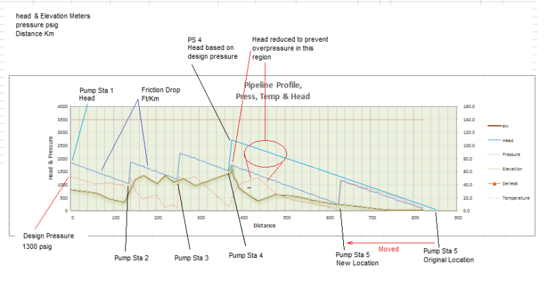
I am trying to simulate a long pipeline for the transport of liquids, e.g. water. The flow rate will be constant and equal to a specific value. The internal diameter will be the same for the entire pipeline. There are elevation fluctuations in the pipeline, the pipeline contains a number of high points and none of them is located near the end of the pipeline. To move the liquid, a number of centrifugal pumps connected in series may be used. The pumps may differ from each other, the distance between them may be very long and the wall thickness of the pipes should be as thin as possible.
If I understand correctly, I should use Bernoulli equation between every two pumps at key points to find the point where the elevation at that specific point minus the elevation of the first pump plus the friction head loss (for the specific flow rate and until that specific point) is maximum. This will be the minimum head that the first pump must provide (minus the head at the inlet of the pump) with the condition that the head at the inlet of the second pump is at least equal to the NPSH required. By checking different pump characteristic curves, I must then select each pump to provide the specific flow rate for its calculated head with the operating point being as close as possible to the best efficiency point. However, if I add the head of all the pumps, the sum may be higher than the total head calculated with Bernoulli equation between the beginning and the end of the pipeline (for the specific flow rate) due to the high points. The system will operate where the added pump characteristic curve intersects with the system curve. So, how can each pump operate at the specific flow rate and also provide enough head for the liquid to reach the high points, by adding a valve just before the end of the pipeline to increase friction loss?
Thank you in advance.

