Continue to Site

Eng-Tips is the largest engineering community on the Internet

Intelligent Work Forums for Engineering Professionals

  • Congratulations KootK on being selected by the Eng-Tips community for having the most helpful posts in the forums last week. Way to Go!

Fluid dynamics 2

Status
Not open for further replies.

Biltwell

Industrial
Oct 18, 2023
31
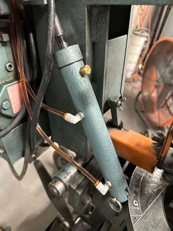
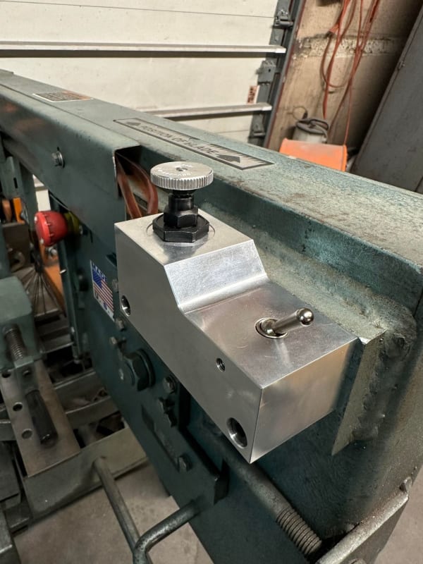
Good day, I am new here and also not much a hydraulic expert but I have recently designed a valve body to be used on a horizontal band saw, This valve replaces a singular needle valve attached directly to the cylinder and now mounted about 36" from the cylinder. In the valve body is a needle cartridge valve with a toggle cartridge valve. The idea is to be able to adjust flow rate while also being able to lock the system completely. And it does work (sorta). When the valve is barely cracked open I seem to be having a flow issue. The fluid will flow for a couple of seconds then slow way down. And Ill have to keep opening the valve more and more until the flow rate is too high and that at that point it'll have consistent flow. I stuck to the same principles as the OEM valve and port sizes, IE 1/8 npt and 1/8 ID line. I've tried using 0w20 oil and that doesn't seem to increase flow rate at all. I could really use some advice/input on this one from someone with more experience than myself. Thank you!
382257187_365590125793338_5091808378594592880_n_l7d8iu.jpg
382319426_698504328874229_633094721056332568_n_ldifby.jpg
 
Replies continue below

Recommended for you

Use a pressure-compensated bypassing flow control. AW 32 hydraulic oil may perform better than 0w20 oil.

Ted
 
I'm not sure how I would implement that into my current design... How does AW32 compare to a 0w?
 
I strongly suspect your new needle valve has different opening characteristics compared to the original valve.

But form a couple of phots it's impossible to understand the dynamics, pressures and what exactly is going on.

Also does the pressure stay the same both sides of the valve?

Does whatever this valve feeds just lock up and hence flow goes down until the pressure builds up then it jerks forward a bit, flow gopes up then it stops again?

We have no idea what is going here....

Remember - More details = better answers
Also: If you get a response it's polite to respond to it.
 
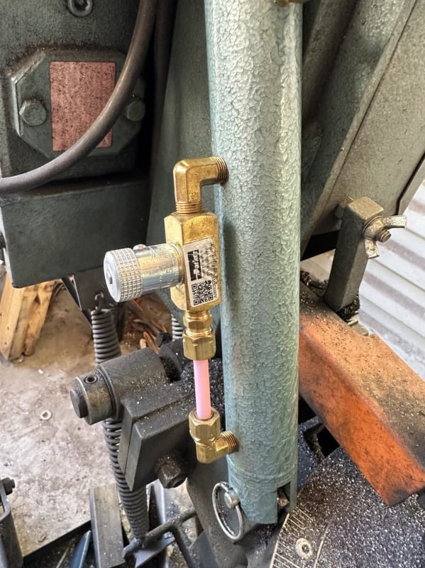
My apologies. The hydraulics control the fall rate of the bow of the saw. It is a double acting hydraulic cylinder. The OEM control is a simple parker inline needle valve that just goes from one port to the next on the cylinder. I have replaced that with this manifold that houses a new needle valve and an on/off valve. The needle valve controls the flow rate of the fluid and the on/off valves completely stops flow so that I can lock the bow in place. IE for when I am loading and/or unloading material. It takes the place of having to open and close and readjust your flow rate each time your loading or unloading material.

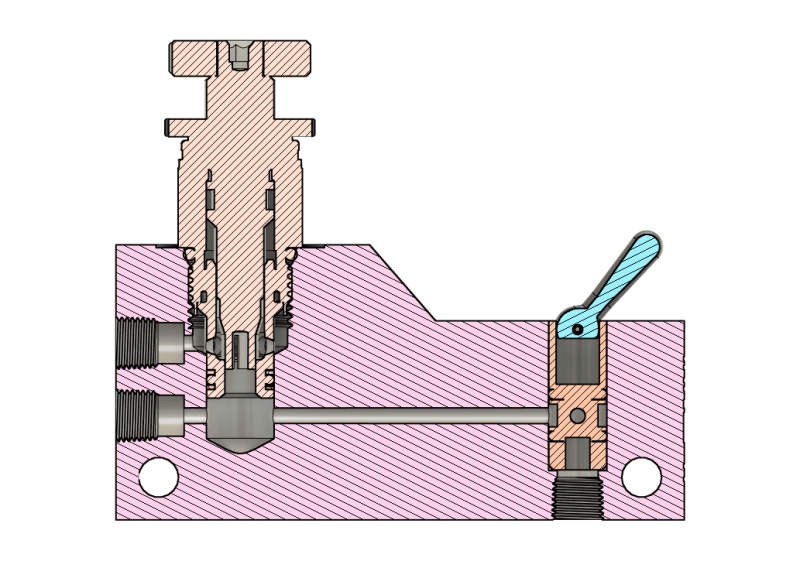
Ill be happy to share any info I can but I don't know what you need to know. I'm a metal fabricator/machinist that had an idea and I'm just trying to get it to work. Picture below is the OEM set up Also an image of a section view of my valve body with the two valves in it.
Capture_ohe0bk.png
393393343_2583947251763783_3799670205557885855_n_orolmh.jpg
 
You need to see the curves for the flow (Cv) vs opening for the two valves.
My guess is that the new valve is mis sized.

= = = = = = = = = = = = = = = = = = = =
P.E. Metallurgy, consulting work welcomed
 
Mis-sized in which direction? Would too large of a valve cause my described issue?
 
ISO 32 or AW32 has a viscosity between the 0w and 20w oil. It also has a higher viscosity index; the viscosity doesn't change as much with temperature.

Ted
 
I think the item to focus on is the pressure in the line upstream and downstream from the valve. When you crack it open, you essentially have a fixed orifice size. If the flow rate is changing during this time, then the pressure upstream and downstream of the valve must be changing. This is assuming there are no temperature changes which given the short time frame, I am assuming to be true. As the band saw moves, pressure in the downstream cylinder will change. If the saw is moving faster than the flow in the hydraulic system will allow, it will jump around, especially if there is any air in the lines.
 
So it seems like you might be saying that the orifice for the down stream would need to be larger than the upstream? Up stream is only When you by hand lift the bow back up and down stream is the controlled hydraulic flow.
 
You have to have an air pocket at the top (rod) end of the cylinder to allow the rod to enter the cylinder without hydraulic lock-up. The fluid displaced by the rod entering the cylinder has to have somewhere to go.
 
I'm still not really understanding this system. It should be simple, but can you draw it out schematically as I can't understand how your new thing allows flow in two directions to move the saw up and down. what is connected to which port?

Remember - More details = better answers
Also: If you get a response it's polite to respond to it.
 
The weight of the cutting saw and blade are countered by the hydraulic cylinder lowering slowly as oil bleeds through the needle valve. A very basic arrangement for a horizontal bandsaw. Cheaper saws just use a spring.
 
The two pictures of the cylinder are different. Which one is correct?

The second one has a simple valve to control flow.

Remember - More details = better answers
Also: If you get a response it's polite to respond to it.
 
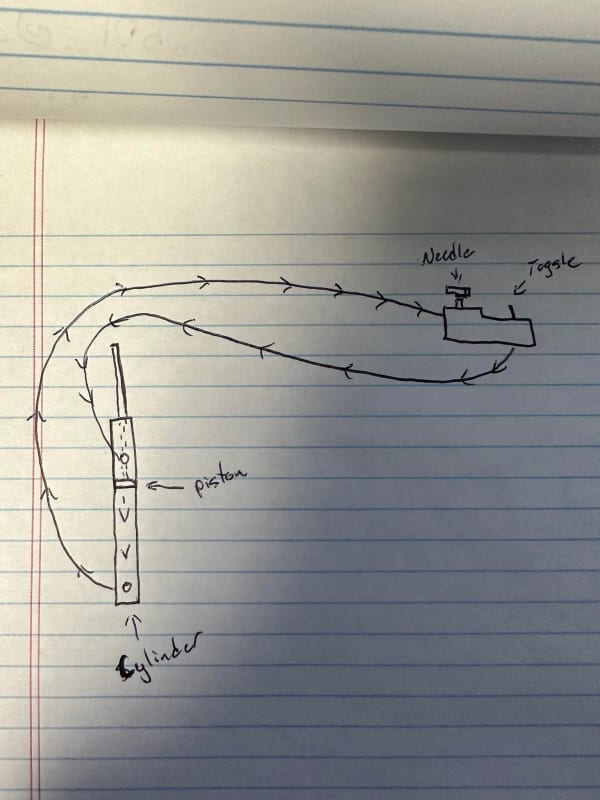
LittleInch, Here's a quick sketch. Inside the cylinder is a leather cup as opposed to a typical piston with seals, this allows fluid to bypass when the cylinder is being lifted up IE when you lift the bow of the saw up and maintains pressure on the downward stroke.
394176177_796543365560294_5636910936965149767_n_zxn26z.jpg
 
So which photo is correct?

Remember - More details = better answers
Also: If you get a response it's polite to respond to it.
 
The one with the oil lines is my current setup, the one with the parker needle valve is the OEM setup.

The hydraulic oil flows through the my valve body being regulated by the needle valve, the toggle on/off valve remains open during downward stroke. It is shut off to obstruct flow only when I want the bow to stay up in place.
 
Ah. Finally ⁴got it I think.

So in your diagram of the new device, which ports are connected to which?

Is the return flow line connected to the to left port on your drawing?

Looks to be the wrong flow. Have you tried swapping the flow around in your new device?

Remember - More details = better answers
Also: If you get a response it's polite to respond to it.
 
So far all the actions I've taken to try and rectify my issue are, Reversed the oil lines to feed in either direction, Bleed system of any possible air, lower viscosity oil, and removing helper springs to increase the weight of the bow. None of which have solved the issue.
 
The toggle valve has a flowrate of 74 GPM and the needle valve has a flow rate of 12 GPM minute. Both of which should be completely suitable for this application. The only thing I can figure now is possibly the return oil line is too constrictive and needs to be opened up some? I am using the same size lines on both the feed and return sides. 1/16 ID
 
Status
Not open for further replies.

Part and Inventory Search

Sponsor