Continue to Site

Eng-Tips is the largest engineering community on the Internet

Intelligent Work Forums for Engineering Professionals

  • Congratulations waross on being selected by the Eng-Tips community for having the most helpful posts in the forums last week. Way to Go!

Fluid Flow Questions. Flow rate vs PSI drop. Min pressure diff across a solenoid valve 6

Status
Not open for further replies.

Rodger Furey

Mechanical
Jun 6, 2023
13
Question 1: Do I need a restriction in each branch of our plumbing?

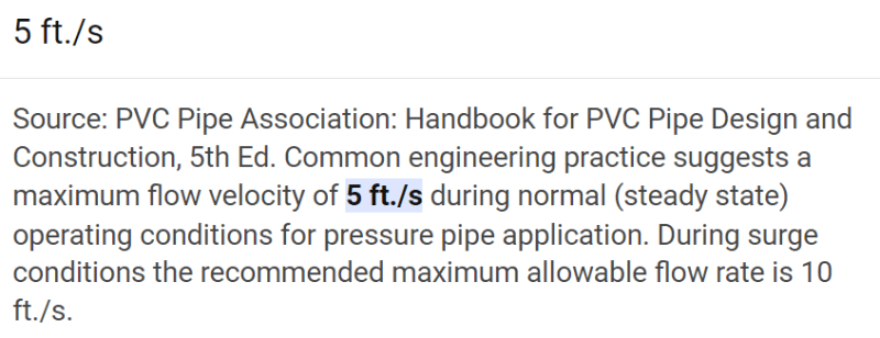
According to a variety of sources, we should be limiting the velocity through our PVC pipes to 5 ft/sec.
5 ft/sec can be translated to GPM for each pipe size.
FPS_to_GPM_tpklkh.png


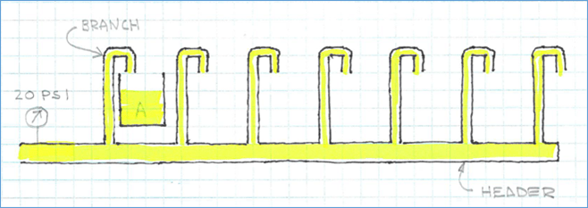
Branch_Plumbing_kamo40.png


If I need to flow 3 GPM thru the branch to Tank A, I can pick a 1/2 IPS pipe and be below the 5 ft/sec … so far, so good.
The problem is the pressure drop from one end of the pipe to the other is usually much higher than needed, resulting in a much higher velocity than desired.
This has caused problems when we use some types of solenoid valves in each branch.

P_drop_100_ft_w9nwoh.png


According to the Hazen-Williams equation, a 1/2 IPS pipe, 100 ft long will flow approx 5 GPM.
Handbook of PVC Pipe Design and Construction (uni-bell.org)
(I am also using the nomograph based on Hazen-Williams to check the calcs.)
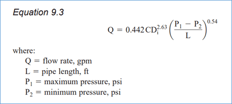
H_W_Equation_xpfg16.png


Our branch pipes are much shorter … say, 10 ft long (equivalent length, factoring in fittings)
At 10 ft of length, Hazen-Williams returns a flow rate of almost 18 GPM, and a velocity of 26 ft/sec
In order to drop the velocity to 5 ft/sec, I only need approx 1 psi pressure drop.
It wouldn't be practical to reduce the pressure in the header to 1 psi.

Question 1.1: Therefore it seems like I should always be installing some sort of restriction in each branch to eat up 19 psi of pressure drop … a gate or needle valve?

Question 2: How do I achieve a 5 psi pressure drop across a solenoid valve?

Branch_w_Sol_Valve_kfv0pt.png


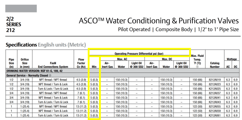
I’m looking at this ASCO valve.

ASCO_d2owxf.png


According to its data sheet, it needs a minimum of 5 psi operating pressure differential.
Well, if I install a 1/2 IPS valve (Cv 4.5) in my 1/2 IPS pipe, I would need to pass 10 GPM through that valve in order to achieve that pressure drop.

Cv_Eq_jaqgeg.jpg

Cv_5_psi_q2n38t.png


If I only pass 3 GPM (5 ft/sec), the pressure drop across the valve is only 0.4 psi.

Cv_3_GPM_jqdaxs.jpg


Question 2.1: What am I doing wrong?

Thanks for any help!
 
Replies continue below

Recommended for you

Question 1.1: Therefore it seems like I should always be installing some sort of restriction in each branch to eat up 19 psi of pressure drop … a gate or needle valve?
I would say, a globe or needle valve; not gate valve.

Question 2: How do I achieve a 5 psi pressure drop across a solenoid valve?
Question 2.1: What am I doing wrong?
I don't understand why an on/off solenoid valve needs a minimum of 5 psi "operating pressure differential". Are you sure about that? The terminology of "operating pressure differential" seems a little strange to me. Did they really mean a minimum 5 psi operating pressure? You have 19 psi. I'd recommend calling ASCO and clarify.

Good Luck,
Latexman

 
Agree with Latexman.

Q 1.1 - Correct. Globe or needle valve. Note a globe valve is very similar to an old fashioned tap or faucet where you control flaw by screwing the tap open or closed. You could also use an orifice plate but the hole would need to be very small and might block.

Q2 - you can't and I think you're confusing Valve CV with pressure drop?
2.1 I think you're confusing valve CV with pressure drop. Nothing you posted says anything about 5psi.

You can use a solenoid valve with a second control valve downstream set to give you 3gpm.

Note that for your header., the header size needs to be quite large if you have 5 or 6 or more branches such that the pressure at each branch is not unduly affected by flow into the branches. A ROT is that the square area of the header needs to be equal to or more than the square area of ALL the branches to prevent getting different flows when you have more than one branch running. It also helps if the branches are close together on the header

Remember - More details = better answers
Also: If you get a response it's polite to respond to it.
 
What type of application is this. Wouldn't you have to have some sort of shutoff valve on each branch anyway? The shutoff valve would then also be used to control flow like a hose bibb valve on a house water outlet. You would not want the flow to just be at any flowrate out of a completely open pipe but be controlled to an amount you really need.

I believe you would size the branch pipe based on the maximum flowrate to the tanks that you need assuming you are going to control the flow with a manual valve to that value. If you exceed 5 ft/sec every once in a while by keeping the valve too far open what does it matter? Why is 5 ft/sec such a limit in PVC? Is this for preventing water hammer? Seems very low. in carbon steel 15 ft/sec is a limit based on erosion-corrosion but PVC does not have this happening.

And why would you need 5 psi across solenoid valve to operate properly. A solenoid valve is an on-off isolation valve not a control valve. It should be able to operate without any differential pressure whatsoever.
 
Oh I see I re-read to notice that you have solenoid shut off valves in each branch. So install restriction orifice plates to limit the flow to 3 gpm or a manual valve as suggested. I don't thing requirement for 5 psi across solenoid valve is correct unless it is specific to the manufacturer you are looking at.
 
Solenoid valves are on/off. When on, flow is variable with the pressure drop across them

Put conventional flow control valves in each branch, with the solenoid to turn on or off each branch.

Excess flow valve? Don't think so. They turn off when set point flow is exceeded. Any flow perturbation at one valve would shut it off. That flow would then attempt to move to other branches, probably increasing their flow rates and stutting their XFV off too. A cascade shutdown.

--Einstein gave the same test to students every year. When asked why he would do something like that, "Because the answers had changed."
 
Op,
You said the design is for plumbing. If it is, then the plumbing design is a different ball game. You can refer to any plumbing code for your jurisdiction.
You also said you want to install solenoid valves. What's the reason? Are you going to introduce some logic for the branches to function?

GDD
Canada
 
Thank you all, for the replies.

I've been waiting for ASCO to explain why their valve needs a 5 psi minimum pressure differential, per their literature. ... still waiting.

ASCO_vrdo6t.png


To answer some questions ...

A number of sources say that 5 ft/sec should be the max velocity through PVC pipe.
It's not a big deal for me to size the piping for 5 ft/sec.

5_fps_jqfthw.png
 
The "pilot operated" bit might be important if that is the motive force needed to pen the valve?[pre][/pre]

Remember - More details = better answers
Also: If you get a response it's polite to respond to it.
 
The 5 fps limiting velocity is based on water hammer or pressure surges due to rapid closure of a valve and sudden stopping of flow. Attached is the plastic pipe institute design manual chapter 6 and a pvc pipe manufacturer manual that discuss limiting velocity based on pressure surges.

The 5 psi differential for the valve appears to be because it is actually a diaphragm actuated pilot operated valve where the pilot valve is the solenoid which opens to allow pressure to be applied to the in-line diaphragm valve to open or close it and it needs a minimum of 5 psi.

Here is link to all PPI publications:

 
So the 5psi isn't a pressure drop, but is the minimum differential pressure when closed to allow it to open.

You might want to find a true solenoid valve where the valve opens and closes due to the action of the solenoid alone.

Remember - More details = better answers
Also: If you get a response it's polite to respond to it.
 
OP,
Your top table assumption of 5 ft/s is correct assuming a constant system pressure.
The pressure differential across the branch pipe is 20 psi. By conservation of energy and applying Bernoulli's equation,the exit velocity will increase because the static pressure had been converted to kinetic energy at atm. Pressure ( 0 psig).

You can apply couple of options and see which option works best:
1. Reduce inlet pressure.
2. Reduce branch inlet velocity to 2 fl/s (minimum speed)
3. How nay branches will operate at a time. More branches you add you will see less velocity in the branches. This is by the conservation of mass or continuity law.

Don’t worry about selecting the right SOV. You will get SOVs operating with 0 psi pressure differential.

GDD
Canada
 
OP,
Try this, instead of working forwards (header to tank), go backwards. First off, I am not sure why you think your solenoid valve needs to be line sized. Use the solenoid valve Cv, to not only set your flow rate but also your needed pressure-drop. Select a solenoid valve based on its Cv not the line size. So Cv=Q/(psid)^-2, your Q is 3 gpm from what I read and your psid is what you have as supply, minus friction losses. So you need to be looking for a solenoid valve with that Cv. This is how basic valve sizing is performed. For more reading, Emerson / Fisher has some great literature on valve sizing.
 
OP,
To add a little more, I made the assumption that you know what a Cv coefficient is. It is by definition the GPM of 60 deg F water the valve can pass at 1 psid. So if you are selecting a valve with a Cv of 4.5 and your desired flow rate is 3 GPM, then you are obviously starting in the wrong place unless you have a very low pressure system.

I will caution to say, this is not the correct method to size all valves and I will again point to the Emerson/Fisher literature for more guidance since there are other issues around choked flow, cavitation and such that need to be taken into consideration. I will say in spite of your best effort, you did arrive where you need to by realizing that to achieve your required flow rate that you needed to lose a certain amount of pressure because valves commonly act as not only "gates" to turn flow on and off but as restriction / flow control devices as well.

One more note of caution, I did not see anywhere in your post where you were addressing or even considering water hammer. Even at 20 psi in a PVC piping system this can occur depending on the dynamics of the system.
 
I am unclear why a valve would have inlet/outlet sizes that requires a reducer fitting at each end of the valve, thus increasing the overall length.
In my applications, space is often at a premium.
With the 1/2 ASCO valve in the OP example, I would need to flow 10 GPM to maintain a 5 psi pressure drop across the valve to ensure proper operation.
10 GPM in a 1/2" pipe is 15 fps.
Too fast.
5 fps is 3.4 GPM in a 1/2" pipe.
The required Cv for 3.4 GPM and a 5 psi drop is 1.34.
ASCO doesn't even offer one of these valves with a Cv that low. (the smallest is a 3/8 valve, Cv = 3)

If I go with the 3/8 valve, Cv = 3, and a 5 psi drop, that puts the GPM at 6.7 GPM
6.7 GPM and 5 fps indicates that the smallest pipe I can use with this valve is ... 3/4"?
Anything smaller would result in too high of a velocity.
Does that make sense? 3/8" valve, 3/4" pipe?
(Note: I've asked these questions of ASCO, and all I get are one sentence replies that don't answer the question)


Rodger,

Not sure if you missed it, but the issue is that your chosen valve type needs a a min pressure drop.

Try searching instead for "Direct Acting Solenoid valves"

Just an example but note in the description "(In order to open or close the valve it is not required to have any pressure difference between input and output)


Remember - More details = better answers
Also: If you get a response it's polite to respond to it.
 
Pilot operated valves are approx 1/2 the price of direct acting valves.
I need to make sure I fully understand the limitations of pilot operated valves before I advise our engineering group to avoid them.
One "problem" the direct acting valves seem to have in common is they are more sensitive to high velocity than pilot operated valves.
If the velocity is above 5 fps, they may not close properly, according to the manufacturers. 10 fps, definitely not.
I have found no such limitations in the pilot operated valve literature.
So, I would need some means to limit that velocity in each branch. Which means another device and additional cost on top of the x2 price of the valve.
Or, an extremely low upstream pressure.

My two choices appear to be ...

A. Pilot operated valve that requires a minimum GPM to operate properly, and piping much larger than the inlet/outlet of the valve to keep the pipe velocity below 5 fps.
B. Direct acting valve that requires a very low upstream pressure, or a flow restrictor, to limit the pipe velocity.
 
Status
Not open for further replies.

Part and Inventory Search

Sponsor