Continue to Site

Eng-Tips is the largest engineering community on the Internet

Intelligent Work Forums for Engineering Professionals

  • Congratulations KootK on being selected by the Eng-Tips community for having the most helpful posts in the forums last week. Way to Go!

footing design

Status
Not open for further replies.

L-H

Structural
Nov 2, 2017
16
Hi,

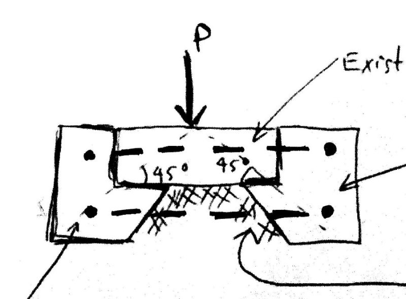
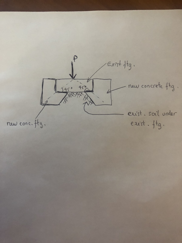
I am trying to find a way to extend the existing square footing to support additional load from the column. I was told that I could follow the idea in the attached photo below. Just dig out some soil at the edge of the existing footing and pour new concrete with some rebars and connect the new footing with the existing by some epoxied dowels. The idea is to utilize the 45 degree dispersion angle and if we can maintain that angle, we don't need to consider the moments in the new & existing footings. Can you guys give some thoughts about this ? I think it will not work that way but don't know how to proof that this idea is wrong.

Thanks
IMG_0015_91_e76bkj.jpg
 
Replies continue below

Recommended for you

Each new piece of the new concrete will want to rotate without being reinforced to resist the rotation, or something else to prevent the rotation.

You need to consider this. Over time, this will not work without the added reinforcing.

Mike McCann, PE, SE (WA)


Can you excavate under it for 3' or 4' every 10' or 12' and underpin it like normal?

Dik
 
What is it that is critical in the design ?
Is it soil bearing capacity or bending capacity of the footing that is critical ?
If its bending capacity then the footing may be reinforced on top with steel channels without the need to dig under which would be very difficult and expensive.

 
Why not add some re-bars and keep this "enclosure" against the footing? Locate them in a form of a hoop.

img105_mosl9h.jpg
 
Hi all,

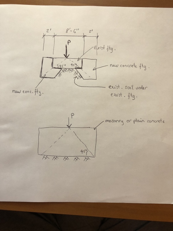
I wanna to add some more info. Please see the attached photo. The existing column is a square 8'8"x8'6"x14" footing supporting 190 kips of load from the column. We are adding one more floor above so the new total load would require the new footing size to be 12'6x12'6. The problem is that in this building there are more than a dozen of columns like this that needs bigger footings. It would cost a lot to shore each column up and pour a brand new footing. So I have been told to explore this idea to extend the existing footing. The reason is that we have seen a lot of footing built with masonry or plain concrete that just rely on the 45 degree dispersion angle of load to distribute the load to the soil. So in the photo I just posted here I have two models, one model for the extension idea and the other model for typical masonry or plain concrete footing. Two models have the same footing size 12'6"x12'6" and the depth to be determined to ensure the load angle to be 45 degree. So could you guys have any idea to explain why the 2nd model works but the 1st one doesn't ? Also does the code allow us to design the footing this big with plain concrete ?

Hi dik: It's a square footing so I cannot do underpinning in segments like strip footing.

Hi oldestguy: we cannot drill through 8'6" of concrete to put rebars at top. If we put rebars at bottom the way you show, we have to drill through the existing soil and disturb the soil and the whole thing will go down ? And we need to protect the rebars with concrete cover also, cannot let them sit in soil like that.


IMG_0018_qouatu.jpg
 
LHONG,

oldestguy is not suggesting any drilling, concrete or soil. The reinforcement he shows is in the collar which you propose, so the bars are in the form of hoops as he said. These bars would be required to resist the tendency of the collar sides to rotate as they are loaded.
 
Hokie66 got it: You could get a little more advantage with a cutting off of the existing footing corners so you somewhat shorten the spanning length for the hoops.

One added thought. What sort of soil are you sitting on and what is the likely change of bearing pressure from the existing likely imposed pressure? Maybe the added pressure caused settlement might be tolerated??? Your present footing may have significantly lower pressure now than that needed to get unwanted settlement. Short of enlarging the footings is there any cheap way to improve the bearing capacity of that soil? I'm thinking of pressure grouting, etc.
 
LHONG said:
The existing... footing supporting 190 kips of load...

It would cost a lot to shore each column up...

Just dig out some soil at the edge of the existing footing...

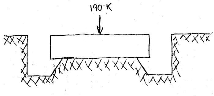
When the soil is removed from under the footing (but before new concrete is placed), the fully loaded (190 kips) footing is sitting on a reduced-size "pedestal" of soil. IMHO, not a good idea. Make an assumption on how wide a band of soil is removed from under the existing footing then do the math to see what happens to soil loading. You may be surprised how much soil loading will increase from removal of a "small" width of soil around the existing footing perimeter.

If the new concrete can be placed successfully, check the punching shear from the column that is now loaded to > 190 kips. I believe you will find that the existing 14" thick footing will have to resist this punching shear.

Without removing the existing 190 kip load (with shoring) before constructing the added footing, I would expect the existing footing to carry all of the original 190 kips and most of the added load.

Excavated_Footing-1_wl4mo0.png


[idea]
[r2d2]
 
Hi SlideRuleEra: 190 kips is the total DL + LL that the existing footing was designed for. But during construction there is only dead load + a portion of live load. 2nd floor framing was designed for 100 psf LL, so maybe we can use 20 psf for construction live load. Thus during construction the total load on the column is not more than 100 kips. I definitely have to calculate how much soil I can dig out during construction.

Hi oldestguy: the existing footing was designed with 3000 psf based on the geotechincal report. The report says we can use 4000 psf for virgin soil and 3000 psf for engineered fill. And from the original foundation plan I found that the interior footings were designed with 3000 psf (I checked it based on the size of the footings and the DL + LL they provided on drawings). So the existing footing may sit on the engineered fill ? If that's the case, i cannot dig out under the existing footing like in the sketch above ?
 
LHONG:
The existing ftg. seems to be a fairly minimal thickness for 190k col. load, but you’ve left out a bunch of useful design info., so who knows. You are a little more than doubling the ftg. area. so the punching shear and ftg. bending moment are not going to be less problematic. You better know how you are going to handle those two design details before you go much further. I would get a local GeoTech involved, and see if there isn’t some easy way to improve the soil bearing cap’y. around the ftgs., as oldestguy suggested.
 
LHONG said:
I definitely have to calculate how much soil I can dig out during construction.

Suggest you do that right now, using a scaled hand-drawn sketch. A conceptual sketch, such as you have provided so far, may look reasonable, but a scaled sketch will begin to point out other problems. For example:

How deep is the excavation under the footing?

As previously stated, how "wide" is the excavation under the footing?

What is the slope of soil remaining under the footing?

How about access to the excavation area? Just how is this excavation going to be performed... by a workers laying on their backs using small trowels?

Another concern... 190 kips or 100 kips, you have told us both. Just because 190 kips is "heavy" does not mean that 100 kips is "light".
IMHO, my earlier comments about the footing "perched" on a soil "pedestal" applies for both loads.

Edit: Suppose it rains after the excavation has been completed, but before concrete has been placed. A heavily loaded soil "pedestal" may have problems.

[idea]
[r2d2]
 
SRE's concerns are well founded, pardon the pun. To be safe, you need to shore the structure above before doing the excavation.
 
Status
Not open for further replies.

Part and Inventory Search

Sponsor