Continue to Site

Eng-Tips is the largest engineering community on the Internet

Intelligent Work Forums for Engineering Professionals

  • Congratulations waross on being selected by the Eng-Tips community for having the most helpful posts in the forums last week. Way to Go!

Force calculation

Status
Not open for further replies.

gersen

Materials
Nov 14, 2017
27
Hello, I'm struggling with a force problem.
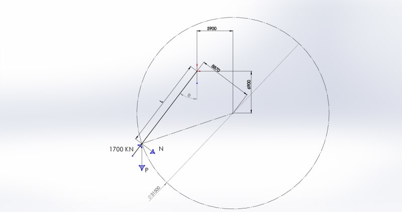
I have a system where a mass P, connected to rod od variable length L. The mass is guided to move on the circumference 31500 mm.
To lift the mass I apply a force of 1700 KN on the same direction of the rod.
What I need to find is the force componet orthogonal to the rod (N), if there is.
Here the scheme:
Parte2_upecxc.jpg


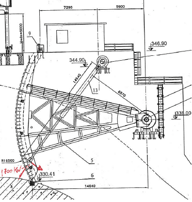
Just for info this is a schematic rapresentation of a radial gate and I'm trying to find the bending stress on the rod, if there is any.
 
Replies continue below

Recommended for you

If you are looking at the maximum bending stress then you need to evaluate the position where this will occur, this will be a function of the orthogonal component of the force and the length of the rod. One location jumps out to me as an obvious point of interest, that of the rod extended to the right exactly horizontally (pheta = 270deg), however there are other candidates for maximum bending stress where the rod length has increased and the orthogonal force has decreased. To calculate the orthogonal component of the force you use trigonometry, which should be covered in a basic statics course. I would suggest graphing the functions of orthogonal force and rod length with regards to pheta and then graphing bending stress as a function of orthoganal force and rod length and evaluating the peak bending stress from the result. Remember to use units consistently, I would suggest using Newtons, meters, degrees, and Pascals for all values.

GSTP

Graduate Mechanical Design Engineer
UK
 
To be more clear this is my situation.
Im_feavxh.png


I need to know if there is bending moment on the rod of the hydraulic cylinder.
I don't know the load, only that I need 1700 KN to lift it.
 
It is not a school problem, it was my curiosity just to know if there is a bending moments but now I know I was looking at it the wrong way. The rod has only axial load because of the hinges.
I am quite rusted on these kind of thinks.
 
furthermore : an hydraulic jack, by definition, can't support a bending moment (really very rusted)
 
If the cylinder isn't moving there can be very high bending moments. Not unusual that the clients require cylinder with few Tons of lateral load on the extended rod.
 
Yes, there is indeed a bending moment on the cylinder, but its not coming from the external load. The weight of the cylinder itself can cause significant internal loads in the extended position if the cylinder is not exactly vertical. I have seen many cylinders wear out prematurely or even lock up from this phenomenon. The actual loading will be from the lateral component of the weight vector. The most common fix is an extended internal stop. Check with the cylinder manufacturer.
 
if the rod is pinned at both ends, and the pins are free to rotate (not seized) then the rod is a two force member, axially loaded.

if the rod ends are not free then there'll be some end moment.

but, in the real world, there's weight to consider and dynamics of the rod, so the rod probably isn't a true two force member, and there'd be bending due to transverse loads (and friction in the joints).

another day in paradise, or is paradise one day closer ?
 
There is no bending moment but the rod can buckle, which can cause plenty of bending.
 
but the rod isn't aligned to the weight vector ... so there is transverse shear (and so bending).

now possibly weight is small compared to 1700kN ... don't know.

and we don't know about the dynamics of this "rod".

another day in paradise, or is paradise one day closer ?
 
Never mind the rod, have you looked at the hydraulic loads on the gate? Could they put the cylinder in compression at any time?
 
Looks like the gate is on an ogee spillway. Better consider flow dynamics as well. What head of water is against this thing?
 
There is something i don't understand. For me 1700 kN is only when you start lifting. After that the force on the hydraulic jack is increasing very quickly and with the jack horizontal the force is infinite (as Grouchy pointed out)
 
I'd've thought it was tricky to balance the hydraulic cylinder compression (change in length) with the force required to move the "gate" ... maybe subtle valving inside the hydraulic cylinder ? Surprised there's no counter weight ??

another day in paradise, or is paradise one day closer ?
 
By the way the directions of the N and P are to what is shown on the first diagram if they represent the tangential and radial components of the 1700 KN value. I suspect that you got the 1700KN by either 1) figuring out this value using the moments about the pivot point of the gate frame when knowing the locations of center of gravity of the gate and of its frame that holds the gate in a circular motion and by figuring out the moment of the frictional resistances at the two pivot points shown in the first diagram or 2)by knowing the load required by the hydraulic piston to lift the gate and its frame clockwise.
To figure out the N and P values, do to SCALE a vector diagram whereby the 1700kn will be the resultant value of N and P.
 
Oops spoke a little too soon, the resultant value will be P whereas the 1700KN and the N are components when using the directions shown in your first diagram.
 
Oh boy!! rereading my first response, the first sentence should read be "the directions of the N and P vectors should be of the opposite directions of what is shown in the first diagram." My second response still stand as long as the directions of N and P are changed to the opposite direction.
 
Status
Not open for further replies.

Part and Inventory Search

Sponsor