Eng-Tips is the largest engineering community on the Internet

Intelligent Work Forums for Engineering Professionals

Force required to lift one end of infinitely long beam 1

Status
Not open for further replies.

tomecki

Mechanical
Aug 18, 2014
18
0
0
CA
I'm trying to figure out the force required to lift up one end of a long pipe by 2m. The pipe is long enough that the entire length of it will not lift off the ground. It will bend under it's own weight and become tangent with the ground at some unknown point away from the end.

I tried to model this using various beam formulas but I end up with two unknowns (the force on one end and the length that lifts off) and can't solve them.


Pipe_lift_bsewhp.jpg
 
Replies continue below

Recommended for you

OK, I think the SS at both ends model is simplified to the point that it is no longer interesting, you've reduced it to lifting one end of a plank off the ground. In order to eliminate the impossible concentrated moment, you've replaced it with a concentrated vertical load of W/2 at x=0, and there is no downward deflection on the beam to create such a force.

However a s;ight;y more complex model is at least intuitively explaining what is happening.

Imagine the SS model, but slowly increase the torsional stiffness of the pivot at x=0. This will force downward deflection into the beam lying on the ground at x>0, which will create the upward W/2 force, and will also raise the beam off the ground at x=0.

So, I think the crucial interesting element is the interplay between the bending stiffness of the beam, and the vertical stiffness of the ground.

Cheers

Greg Locock


New here? Try reading these, they might help FAQ731-376
 
Greg - the "infinitely stiff" support is just a limit to make the calculation easier, but with realistic soil stiffness the results are very close to the rigid results (as shown by both my results and those of avscorreia).

Suppose you had a pipe/plank resting on "point" supports, and were asked to calculate the span length such that if the left hand end was lifted by 2 metres, the right hand end would be rotated to horizontal. Would you still insist that we should consider the finite width of the supports at each end, and the resulting bending moments at the supports?

Doug Jenkins
Interactive Design Services
 
The question was what force was required to lift the pipe by 2 metres. The simply supported analysis gives a good approximation for reasonably stiff ground, and an upper bound force even if the support is very soft.

Here's the simply supported analysis, showing deflected shape for the horizontal pipe and pipe lifted by two metres, which rotates the right hand end to horizontal. I have also attached the spreadsheet.

Pipe-def3_cfrfrb.png


Doug Jenkins
Interactive Design Services
 
how are you accounting for the gradual application of the ground support ?

The point to my second graph is there's a point on the infinitely long pipe where there is no effect from the lift, ground support force = weight. At this point you can have a SS beam. This is someway to the right of the lift-off point. The lift-off point is still (for all intents and purposes) a cantilever support.

This gradual variation in ground support could be a simple linear dist'n, but my money is on (as someone posted above) a more complicated non-linear dist'n (decaying cosine wave ? possibly a decaying exponential dist'n). But then goes to do you want the Right textbook solution or something near enough ?

As for displacement, how do you keep it linear for a portion, near the RH support ? by adapting the distributed load. and it needs to be linear with some relationship to the lift distance (horizontal from the SS point to the lift-off point, compared to the vertical lift of the LH end).

another day in paradise, or is paradise one day closer ?
 
As mentioned by others, 2 meters is a lot of deflection for a real pipe... but will put that aside.

Here's a 2-step, simple model for an accurate solution using hand calculations:

Step 1:

Turn the 
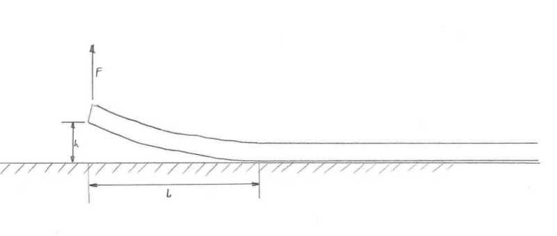
OP's problem upside-down (The pipe does not care, it's structural properties are symmetric and applied load is gravity. Assume the pipe "sticks" to the upside-down flat surface beginning at the tangent point).

Consider the upside-down pipe to be a cantilever beam. While upside-down, for any value of deflection "h", force "F" = 0 (when upside-down, the uniformly distributed self-weight of the pipe, over length "L", causes deflection "h").

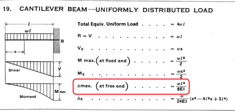
For a pipe with known properties, "w", "E" and "I", calculate length "L" for the proposed 2 meter deflection:

Cantilever_Beam_-_UDL-1_zpxnh3.png


Step 2:

Flip the model back right-side-up. Now the the pipe is represented by a "deflected propped cantilever".

When the problem is right-side-up, force "F" is no longer zero. Instead, "F" is the force needed to deflect the pipe (of length "L", calculated above) into the correct shape (calculated above).

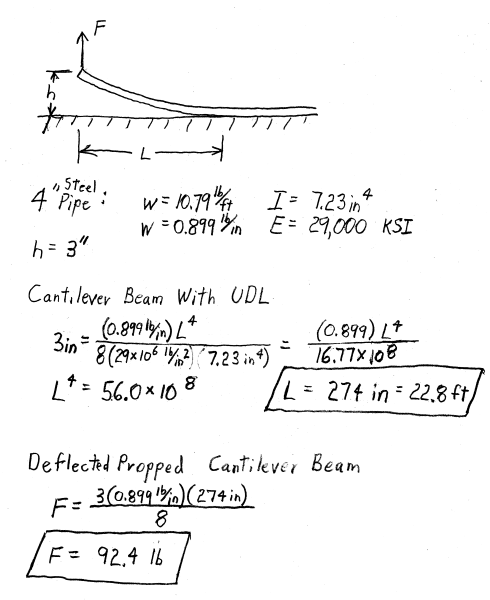
Using the pipe's known properties and length "L", calculate force "F" (shown as R[sub]1[/sub] on the diagram below)

Beam_-_Fixed_-_Support-1_zqy3y4.png


I'm not skilled with metric, so an example with modest deflection in US customary units is attached. Here is an image of the attachment:

Example-1_uqnpi6.png


[idea]
[r2d2]
 
Sorry, but I disagree that it's a cantilever. The fact that the rotation is zero at the support doesn't mean that you have any stiffness to generate a moment. The ground does not generate a bending moment at the point of contact as it only allows compression, as Denial so elegantly demonstrated and as the numerical results show.

Regarding the force distribution at the contact with the ground, here are some additional results for the analysis cases I presented earlier:

Reactions_c4x1mz.jpg
 
is the force to lift fairly consistent ? From the graphs, I'd expect 1E12 and 1E6 to be very similar, and 1E3 to be a little lower (since slightly less pipe is being lifted).

what happens if you don't constrain the model at 60m ? (or if you did at 120m ?) If think the results show not much difference (since things look well behaved at 50m).

Is it interesting that peak soil pressure seems to happen at the same point, regardless of soil stiffness ? could this be an equivalent cantilever length ?


another day in paradise, or is paradise one day closer ?
 
The force to lift is very consistent. I got 42.3 kN for all cases (as I think it should, since the portion of the pipe that is not in contact with the ground is a statically determinate system).

There are some variations in soil pressure along the entire length for 1E3, so a larger length could probably stabilize it a bit, but I don't think it would be too significant.

The resultants of the peak stresses at ground contact do seem to be located around the same point. I don't know about an equivalent cantilever, as there is only support on one side, but maybe we should think of an equivalent support length.
 
SlideRuleEra - I know, but you can't have a moment there as there is nothing there to properly constrain the pipe, so the concept is different from lateral load calcs on piling.
 
I modeled Avscorreia's problem in STAAD.Pro and got the same results as he did. Tomecki, if you will give us an actual pipe size and material I can plug those in and see what I get. Unless, of course, you're just wondering how to solve this problem but you have no real world application.
 
WOW! I just came back to this thread after moving on to something else for a while. Thanks everyone for contributing. I thought it was an interesting problem too, but I had no idea it would generate so much discussion. Might be a good one for a physics contest - simple question, takes a lot of thought to analyze.

Dozer, this is actually a real problem. The pipe is 36” DR9 HDPE:

OD: 36”
ID: 28”
HDPE SG: 0.958
Contained Fluid SG: 1.1
E: 130,000 psi

The manufacturer says that the pipe can be bent to a 60 ft radius so I don’t think this lift will overstress the pipe, although I haven’t actually checked the stresses in the pipe yet.

My results using the simply supported model were: L = 770 in and F = 14,770 lb.
Using the cantilever model with F = W/2: I got L = 763 so F is similar.

Bonus points: This pipe is actually floating in water, but I thought I’d start working on a solid support model for a conservative result.

Extra bonus points: The combined SG of the contained fluid and pipe make it sink, so it’s supported by floats.

Thanks again for your help everyone!
 
Status
Not open for further replies.
Back
Top