Continue to Site

Eng-Tips is the largest engineering community on the Internet

Intelligent Work Forums for Engineering Professionals

  • Congratulations waross on being selected by the Eng-Tips community for having the most helpful posts in the forums last week. Way to Go!

Forces considered in bolted connections 3

Status
Not open for further replies.

Sandychan

Structural
Sep 25, 2015
22
Hello All,

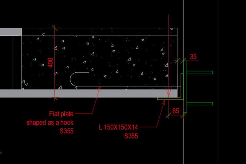
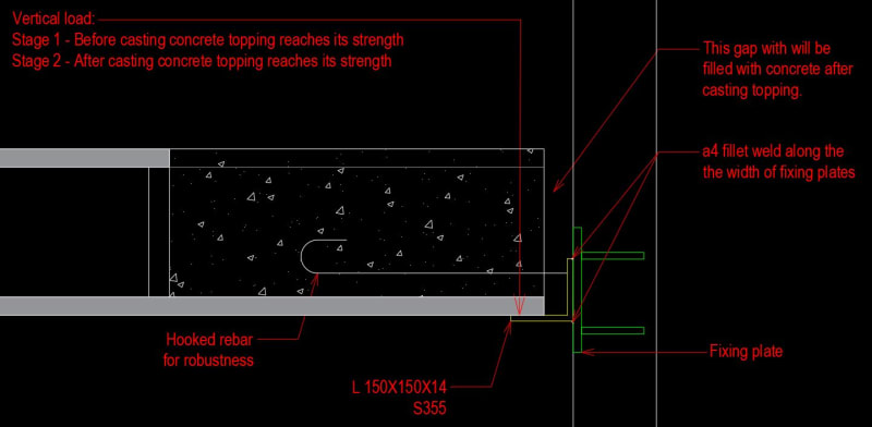
I have a situation where I need to use an angle beam to support hollow core slabs. The angle beam will be welded to fixing plates that will be pre installed in a cast-in- place concrete wall. Each fixing plates have 4 bolts providing anchoring to the wall.

For the design, I have been suggested to consider 2 design stages, before and after concreat topping reaches its design strenght. The loads and design actions to the fixing plates of each stage are as followed:

Stage 1- Before the concrete topping reaches its design strenght

Only hollowed-core slab weight + concrete topping are concerned.

The vertical load in this stage will create shear and moment to the bolts of fixing plates.

Stage 2- After the concrete topping reaches its design strenght

Hollow core slab weight + concrete topping + super-imposed dead load + super-imposed live load are concerned.

The vertical load in this stage will create only shear to the bolts of fixing plates. This is because once the concrete in the gap between the angle beam and the hollow core slab ends reaches its design strength, the angle beam will not be able to tilt forward. As a result, it will not introduce tension to the fixing plate bolts.

Questions:

1. Do you agree that there will be on shear applying the bolts in Stage 2 because the concrete in the gap will prevent the angle beam to tilt forward?
2. I also need to consider robustness case where there will be a vertical load on the angle beam and tension the hook rebar. In case the concrete in the gap has reached the design strenght, then again it will be just shear from verical load applying to the bolts? In other words, the tension in the hook rebar will not do anything to the bolts?

Thank you so much in advance for your answers.
L_profile_connection_dfql19.jpg
 
Replies continue below

Recommended for you

Let me preface by saying that at first glance, I would not trust the outstanding horizontal angle leg to support hollowcore planks of any appreciable length.
The angle leg bent about its weak axis will begin to rotate, resulting in less bearing area as it rotates and a P-delta effect will ensue.
But, to answer your questions, there will be shear on the bolts (I assume you mean studs)in both cases. The concrete in the gap will not eliminate the shear or moment.
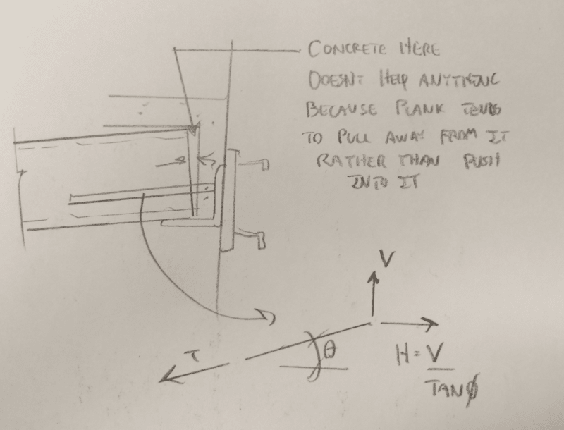
The horizontal leg will rotate and as the hollowcore deflects, it will simply pull away from the concrete in the gap. The stages you describe above simply increase the load.
Increasing the load and filling the gap with concrete will not change the load path (unless something fails). Also, it does not appear possible to weld the hooked bar to the angle.
 
I mostly agree with MC.

OP said:
1. Do you agree that there will be on shear applying the bolts in Stage 2 because the concrete in the gap will prevent the angle beam to tilt forward?

I do not agree for the same reason that MC gave. The plank end is rotating away from the infill concrete. As such, there's no way to mobilize the concrete in compression which is the only way one can really use concrete.

OP said:
2. I also need to consider robustness case where there will be a vertical load on the angle beam and tension the hook rebar. In case the concrete in the gap has reached the design strenght, then again it will be just shear from verical load applying to the bolts? In other words, the tension in the hook rebar will not do anything to the bolts?

This is difficult to answer without knowing the what your local code has in mind for the purpose of those robustness bars. I can envision two options and neither would be just shear:

1) The bar is just a lateral tie between the plank and the wall. In this case the only load on the embedment is tension.

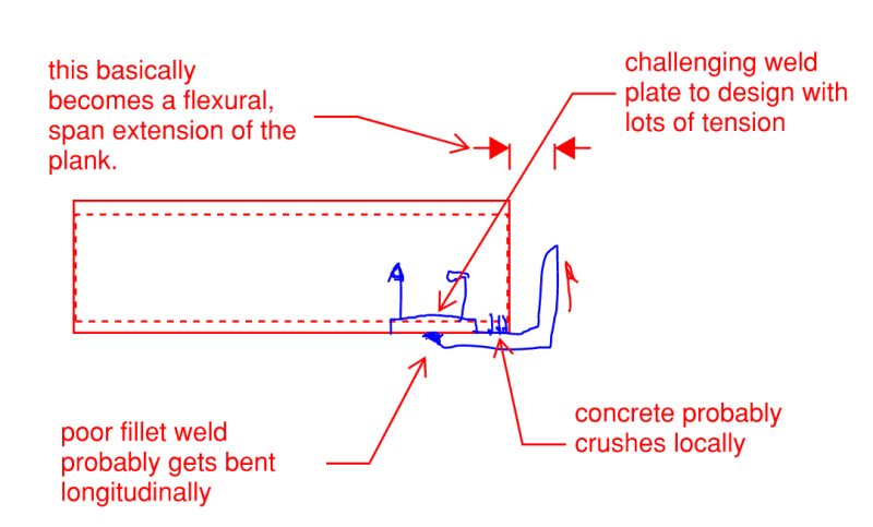
2) The bar is what we in North America would call integrity reinforcement. The idea is for the floor slab to retain vertical support in the event that the bearing angle is lost. In this case, per the sketch below, you would have both shear and a relatively monstrous amount of tension applied to the embed.

C01_tmpcn7.png
 
MC said:
I would not trust the outstanding horizontal angle leg to support hollowcore planks of any appreciable length.

1) Yeah, in my heart of hearts I feel the same.

2) Having done a lot of delegated plank engineering I can tell you that this detail is suprisiginly common for situations where significant spans and loads are involved. And successfully so it seems.

MC said:
The angle leg bent about its weak axis will begin to rotate, resulting in less bearing area as it rotates and a P-delta effect will ensue.

I see pretty much the reverse of that with respect to P-delta. I feel that the centroid of the plank reaction moves closer to the wall with increasing load. As such, the lever arm on the plank reaction decreases with respect to bending in the horizontal angle leg. In my mind this is the opposite of P-delta wherein displacements tend to amplify bending moments from those calculated on an undeformed structure.
 
Would you distrust beam seat connections? I think you can make this detail work fairly easily, as it is essentially an unstiffened beam seat with likely lower load as the angle covers the width of the panel. I don't like the hooked bolt because it could transfer moment, and with that small lever arm cause concrete to fracture somewhere.
 
...as it is essentially an unstiffened beam seat with likely lower load as the angle covers the width of the panel.

Comparing this detail to an all steel, beam seat detail, I would consider this to be much worse because:

1) Brittle, concrete anchorage is involved.

2) You have plank that wants to deliver a lineal load but a seat angle supported only intermittently by embeds.

3) To the extent that the angle between embeds picks up load, the angle experiences a bunch of icky torsion.

4) Relative to steel, the horizontal angle leg will be longer for precast, inducing more moment.

5) Depending on how the plank is loaded, you can pretty easily wind up with torsion on the embed plates.

6) Concrete has nowhere near the bearing strength of steel so you wind up with the center of the reaction closer to the tip of the angle load with concrete.

7) Your average plank is going to have more flex in it than your average steel beam which, again tends to push the load toward the tip of of the angle until it yields flexural and rotates to match.


I must admit that that I don't understand the questions, what bolts? I have no issue with the angle as long as it is checked for rotation and deflection.

However this type of connection is not typically in my location due to the limited fire ratings for the angle, unless the building is full steel and we have a painter onsite.
 
I can't find any fault in the previous arguments against this, but I've seen this detail beeing used several times (also for excentric beams loaded on one side). I also saw an worked example years ago from a hollowcore producer, that is no longer available online, where they argued "shear only".

As I recall the logic for shear only was simply that the angle can't (physically) rotate when the concrete in the gap is filled. Probably based on the expected low deflection in the slab, so the moment produced by the eccentric loading is counteracted by compression in top and tension in the rebar. The details I've seen have been with vertical bars or plates welded to the angle and u-shaped rebar extending in to the hollowcore.
Not saying this is correct, and I no longer have access to the example, so my recollection might be off. But interesting discussion, as this concept is used a lot in my area, especially for one sided steel box profiles.
 
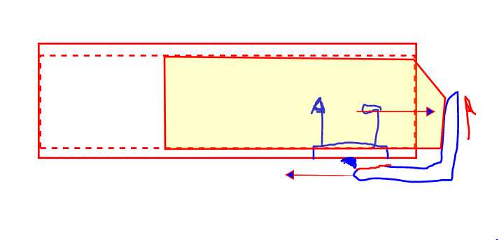
Precasters will sometimes tell this story in order to sell a shear only connection. However:

1) There's plenty to not love about this as well and;

2) I still don't see the concrete fill helping appreciably.

C01_gss7a8.png
 
Similarly, one might tell this this story which does make use of the grout. However:

1) Man, you'd better be right about the plank not rotating much.

2) I'm not sure that the grout is stiff enough to make this story true.

3) Odds you'll just push the grout plugs down the plank cores anyhow with this kind of compression pushing into them.

C01_ohd493.png
 
First of all thank you for your answers.

@Motorcity,@Kooth,@canwesteng, I personally feel ok with the horizontal leg of the angle beam supporting hollow core slab. The deflection in ultimate limit state of the beam's leg is only 1.5 mm. But, the idea of considering only shear the fixing plates' studs made me feel uncomfortable.

@rowingengineer, the bolts I mentioned are the studs welded to the back on the fixing plate (A green piece on the sketch. Sorry for using the wrong word. The deflecion of the beam horiontal leg is 1.5 mm in ultimate limit state.

@wth, The deflecion of the beam horiontal leg is 1.5 mm in ultimate limit state. I don't know if this is considered low delection when the lenght of the beam leg is 150 mm. It is interesting to see that this "shear only" argument has been heard by someone. I just wish I could be more comfortable believe it.
 
Wth,
Nice article, I think the same principles can be used in the design of the angle.the flange thickness used in the tests is similar to the angle.

The question on the stud load will be found by the strut tie model.
 
rowingengineer said:
I think the same principles can be used in the design of the angle.the flange thickness used in the tests is similar to the angle. The question on the stud load will be found by the strut tie model.

I doth protest. The rather massive difference between an edge beam and a ledge angle is that;

1) The edge beam is free to twist over its entire span to match the end slope onf the plank (exceed it really) and;

2) The ledge angle will have rigid torsional restraint at close intervals such that it cannot match the end slope of the plank.

That difference changes the character of the problem significantly.
 
KK,
Your going to have to dumb it down for me. what is the obvious point of your statement that I am missing?

Is it? The hook and the concrete don't form a strut and tie to deliver the load to the radius of the angle? Cue a KK strut tie diagram please to show me why the strut tie doesn't form.

Or

Is it? The lack of rotation means that the plank slope cannot be matched- I am assuming that your saying that this means the load from said plank will be at the edge of the angle flange in stage 1 I agree, but in stage 2 it doesn't matter the concrete is doing the work once set, and yes in stage 1 the angle needs to be designed to take the load of the plank and topping slab or propping provide. But this isn't a hard calc and at 14mm thick flange should be ok.


Some extra food for thought, What happens with the so called edge beam when it is loaded both sides and is no longer and edge beam but an internal beam with no torsion? Does this mean extra testing, I am sure there is a paper somewhere if I look for it that shows this setup.
 
rowingengineer said:
Cue a KK strut tie diagram please to show me why the strut tie doesn't form.

I'll come up with some new and persuasive sketch if I gotta but, because it's you, I'm going to take one last stab and getting it done with verbiage. Take that as the complement that it is.

rowingengineer said:
Is it? The hook and the concrete don't form a strut and tie to deliver the load to the radius of the angle?

1) The tie cannot form unless the strut also forms.

2) The strut cannot form unless the support angle is torsionally flexible enough that it rotates until it bumps into the plank/grout.

3) I submit that:

a) a typical, open cross section beam is torsinally flexible enough between it's vertical supports for this mechanism to form. Both the plank end and the supporting beam rotate and, crucially, the beam rotates faster such that it eventually bumps into the plank/grout.

b) an angle, rotationally restrained at the supporting wall at 2'oc - 4'oc is not torsionally flexible enough for this mechanism to form. Both the plank end and the supporting angle rotate but, crucially, the plank rotates faster such that the angle never bumps into it.

rowingengineer said:
Is it? The lack of rotation means that the plank slope cannot be matched- I am assuming that your saying that this means the load from said plank will be at the edge of the angle flange in stage 1

Yes, that exactly.

rowingengineer said:
I agree, but in stage 2 it doesn't matter the concrete is doing the work once set, and yes in stage 1 the angle needs to be designed to take the load of the plank and topping slab or propping provide. But this isn't a hard calc and at 14mm thick flange should be ok.

This would seem to be where we disagree. I feel that, before the angle would rotate enough to bump into the plank end in stage two, these two, horrible, brittle outcomes would come to pass:

1) The welds connecting the angle to its embed supports would fail.

2) The the embed itself would fail under the imposed moment + shear.

rowingengineer. said:
Some extra food for thought, What happens with the so called edge beam when it is loaded both sides and is no longer and edge beam but an internal beam with no torsion?

I agree completely with your concern. Moreover, most true edge beams will be endowed with a fair amount of torsional restraint at their ends. As such, I suspect that you have the nifty strut and tie mechanism in play in the middle of the beams but not near the ends.
 
rowingengineer said:
I feel that, before the angle would rotate enough to bump into the plank end in stage two, these two, horrible, brittle outcomes would come to pass:

1) The welds connecting the angle to its embed supports would fail.

2) The the embed itself would fail under the imposed moment + shear.

I suppose that one could capacity design these brittle things for the plastic yield capacity of the horizontal angle leg. 1.25 Fy etc. I suspect that would lead to some substantial anchorage forces however.
 
Hi everyone,

Thank you for ffurther discussion. I talked to my senior who suggested me this shear only idea again and it turned out that I misunderstood him. In his opinion the loads applying to the slab after the topping concrete reaches it design strenght also introduce moment to fixing plate studs but with small amount. The eccentrictiy of such loads is equal to the thickness of the L beam. In my case it is 14 mm.

For the first stage the position of load resultant for hollow core slab+concrete topping is considered to be at 50 mm from the end of slab. The gap between the wall to the end of hollow core is 35 mm. As a result, the eccentricity of hollow core slab+concrete topping load is 85 mm. So the total moment applying to studs according to Eurocode load combination is as followed:

Total moment= 1.35*(Hollow core + Concrete topping)*0.085 m + (1.35*Super-imposed dead load + 1.05* Live load)*0.014 m

The hook presented previously turns out to be flat plates shaped as a hook to act as horizontal ties. I have to confess that I am still confused with this whole thing but my senior sounds pretty firm with his suggestion. So, I will just go with that. Justification about eccentricity of the loads after casting concrete topping makes me feel more comfortable with this design.

HDF_support_mhb6nz.jpg
 
Status
Not open for further replies.

Part and Inventory Search

Sponsor