Continue to Site

Eng-Tips is the largest engineering community on the Internet

Intelligent Work Forums for Engineering Professionals

  • Congratulations KootK on being selected by the Eng-Tips community for having the most helpful posts in the forums last week. Way to Go!

Forces in Chevron brace 1

Status
Not open for further replies.

Nitesh Sadashiva

Civil/Environmental
Jan 9, 2020
33
Hello all,

This seems to be pretty basic. But I always had this doubt while designing chevron brace connections. Usually the forces in chevron braces will be indicated with +/-. So the chevron braces can be either in tension or compression. While designing connections, we will consider all possible cases such as both braces in tension, both braces in compression, one in tension and other in compression. Considering both chevron braces in tension or compression will result in heavier connection. Is it correct to consider both braces in tension or compression? I believe on should be in tension while other brace will be in compression. I appreciate if you can clarify this.
 
Replies continue below

Recommended for you

Typically, I only consider the scenarios where one brace is in tension and one in compression. Considering both braces to be simultaneously in tension or compression often results in significant, perhaps unnecessary, reinforcement of the supporting member. If you are not the EOR, the design method can be confirmed with an RFI (preferred) or later on during calculation approval. The Seismic Design manual is a great resource for vertical bracing connections, and incorporates more modern methods/publications than AISC Design Guide 29.
 
Gravity loads can readily load both braces in compression or tension and and ignoring it be quite problematic. Reverse chevron or 'V' brace can readily load the members up in tension putting significant loads on the connections an axial loads on the member above.
 
There are certainly instances where both braces could be in tension, or compression, for a chevron brace. What about the situation with no wind but full gravity? Is it a roof chevron or a floor chevron? If roof, what about wind uplift but no lateral on that frame line, that would give both in tension. Albeit in my two scenarios, the loads are likely far less than your current design loads.
 

Can you do that?

So strange to see the singularity approaching while the entire planet is rapidly turning into a hellscape. -John Coates

-Dik
 
I guess it depends on the design intent for the structure. I'm biased toward heavy commercial/industrial structural steel, where the vertical bracing is part of the LFRS 99% of the time.

In my experience with delegated connection design, the EOR will prescribe worst case design loads or full brace-member development. Working in the magnitude of hundreds, sometimes thousands of kips, aligning the maximum forces in CC or TT would result in the support member being totally inadequate. Usually the intent/load-path is confirmed in the kickoff meeting.

If I was working on a wood or steel mom & pop structure, I could see gravity loads or some kind of uplift resulting in a CC or TT scenario.
 
DrZoidberWoop said:
I guess it depends on the design intent for the structure. I'm biased toward heavy commercial/industrial structural steel, where the vertical bracing is part of the LFRS 99% of the time.
Except the actual loads don't depend on the design intent. The loads will follow the stiffest load path and diagonal braces are far stiffer than a horizontal beam for gravitational loads. (unless you get very early elastic buckling of a chevron brace in compression) If the design intent of you bracing is for restraining lateral force but the gravity loads are not considered then you could readily overload you braces (less of an immediate concern) or your beams and columns (more of a concern).

DrZoidberWoop said:
In my experience with delegated connection design, the EOR will prescribe worst case design loads or full brace-member development. Working in the magnitude of hundreds, sometimes thousands of kips, aligning the maximum forces in CC or TT would result in the support member being totally inadequate. Usually the intent/load-path is confirmed in the kickoff meeting.
That sounds like a reason for better communication. Not a reason for ignoring the gravitational or other CC/TT loads on chevron bracing.

DrZoidberWoop said:
If I was working on a wood or steel mom & pop structure, I could see gravity loads or some kind of uplift resulting in a CC or TT scenario.
I don't see that as a more likely area of CC/TT in such bracing. I work in industrial structural steel with chevron bracing and I regularly need to consider compression loads because it is naturally the stiffer load path.
 
There may be some load cases that induce CC/TT in the chevron braces, but for a normal proportioned structure and LFRS, the maximum brace force is normally due to lateral loading. I guess I'm just saying if there is a CC/TT load case it is likely going have alot lower force in each brace than the lateral case, and in the lateral case you have forces in opposing directions in either of the two braces in a normal chevron configuration.

Seems to me that if you take the maximum brace force from a lateral load combination then apply that force in simultaneous tension or compression with both braces that isn't really a design load case.
 
I would say the vertical bracing is part of the LFRS all of the time as well. The situations we pointed out are just different load cases to be considered. If they weren't part of the LFRS, why have them. I agree though that it's unlikely to be a controlling load for the rare cases where it's CC or TT.
 
There are a number of different design considerations for Chevron Braces, especially when considering seismic:
a) Gravity load cases, where both braces are in compression. Certainly the connections need to handle this case. But, just as importantly, the BEAM above the Chevron should be able to handle this case. The idea being that you may have to replace the braces themselves after an extreme event. Or, that the braces may fail during an event.

b) For the seismic (or wind) portion of the load, it will generally be one brace in tension and one in compression.

c) Seismic detailing for failure. This is when things get interesting like designing for one braced to have buckled while the other brace is in it's worst case tension loading.
 
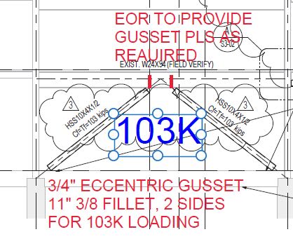
One of my more recent projects:

Clipboard01_covmpe.jpg


So strange to see the singularity approaching while the entire planet is rapidly turning into a hellscape. -John Coates

-Dik
 
driftLimiter said:
There may be some load cases that induce CC/TT in the chevron braces, but for a normal proportioned structure and LFRS, the maximum brace force is normally due to lateral loading.
Some of my structures object to you suggesting they are not normal proportion! [rednose]

In all seriousness you can readily get gravitational loads that exceed the lateral loads and the peak load will normally include gravitational. You cannot say one way or another without analysing the structure. For my 6 storey industrial building I have here I get 122kN&110kN(C&C) gravity combination in one pair of Chevron braces on the ground floor and 190kN&-51kN(C&T) wind combination. Yes the lateral load has a higher peak force but if you are designing the connection I would not forget about the 122kN&110kN(C&C) compression load on the connection.
 
We all seem to be mostly in agreement here. I guess what would be important is to understand the load cases causing the forces, and for EOR's we aught to be specifying out all of the applicable loading to the connection designer. In my area delegated design of connections is not allowed so I haven't had to worry about that part of it before, also in my area the seismic demands are very high so I guess what is 'normal proportion' to me is totally subjective, fair point @human909
 
Yes I believe so.

The influence of high seismic makes sense and means a different perspective. And like many conflicting comments on this forum they come about due to different perspectives and different experiences of those involved. Honestly exposure to this is a good part of learning.

Honestly now that I think about it I've used the knowledge that compression and tension will occur together and cancel out in several designs where the lateral braces are attached to the walls of HSS, eg a tall unclad stair tower. Since I do my own connection design I know that you aren't going to have TT or CC together so excessive load on into the plane of the HSS wall is not a problem.
 
Thank you all for your valuable input. From the above discussion what I understand is, since I am responsible for delegated connection design, either I need to consider all possible cases in connection design which is conservative or I should clarify with EOR whether I can ignore TT or CC cases. It is not correct to just assume T-C case. In design drawing it is not clear whether the provided brace forces are due to lateral load or due to gravity. I feel it will be better if EOR shows gravity loads and lateral loads separately at least for chevron braces. This will definitely save the cost. I believe everyone agree with this.
 
Yes, I think we can all agree with that. I apologise if my disagreement with others led things a little off track.

In some structures designing for TT or CC would be excessively conservative, in others not at all. With the information provided by the EOR you cannot know. To put it explicitly TC has a higher shear demand on the connection than TT or CC whereas TT and CC have a higher axial demand.
 
Nitesh,

Being responsible for designated design puts you in a tough spot. The most efficient way (from a material used perspective) to design your chevron connection would be to go through each load combination and perform the analysis. But, you will likely not get that information. In addition, if you aren't using a semi-automated connection software, you'll spend oodles of time trying to get all the different load combination forces input into the program.

So, you can either RFI (as indicated in your latest post), or you can design it for the CC, TT, and both TC cases. Then, when the EOR and/or contractor freaks out about the size of the connection, you can point out that all you were given were brace loads, not appropriate combinations of those loads. I'm partial to option 2, as I'm a big fan of learning opportunities.
 
I agree @human909 @winelandy. Unfortunately, sometimes ego between the engineers comes ahead of the execution of the job. We become little reluctant to listen to the fellow engineers and stick on to our statement. If everyone in the line starts from design to execution, co-ordinates and discuss the things, the overall project will be benefitted. I am glad I found this forum to discuss and share the things. Once again thank you all.
 
Status
Not open for further replies.

Part and Inventory Search

Sponsor