Hi all,
I've been doing some checking of some older fabricated trestles at work to check load ratings etc. See the attached image for a welding trestle. I have been using FEA so we have a report record etc. Anyways, so far all have been 2D planar members for legs - as in if you look at the end view of the trestle the legs are 2D so it would be simple statics to work out the force in each leg of the trestle.
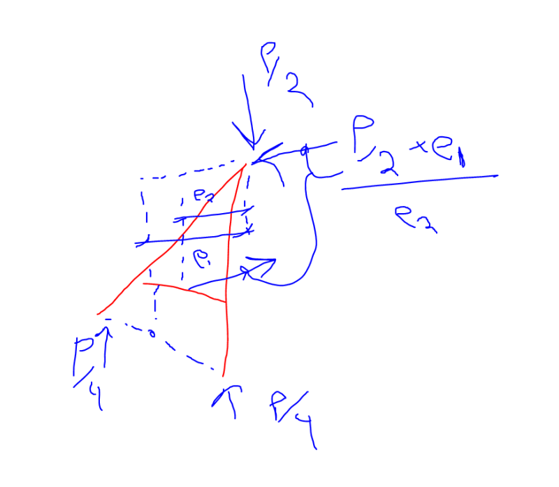
One I checked today wasn't planar - the legs were angled out in the y and z direction, so if you look at the end view it's not 2D. If I wanted to calculate the force in each leg do I need to use vectors or is there a simpler method?
Trying to remember back to my statics days ...
It's easy enough to resolve a weight on the trestle to two point loads on top of each set of legs. What's the easiest method to use from there?
Cheers guys

