Continue to Site

Eng-Tips is the largest engineering community on the Internet

Intelligent Work Forums for Engineering Professionals

  • Congratulations KootK on being selected by the Eng-Tips community for having the most helpful posts in the forums last week. Way to Go!

Forces in scissar lift

Status
Not open for further replies.

Agunia

Student
Dec 29, 2020
4
jack_n6fkit.png


Hi

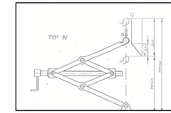
I need help, how can i calculate force in screw and in rods ?
 
Replies continue below

Recommended for you

A clue, draw some free body diagrams, then post what you have done and then we might help

“Do not worry about your problems with mathematics, I assure you mine are far greater.” Albert Einstein
 
IMG_20201230_133029_1_chw062.jpg


I think direction of Rb force is correct but Ra is not. Only 2 unkown forces Ra , Rb so i didnt use sumM=0. I think im doing huge mistake.
 
Hi

Where are the dimensions of the scissor lift ? There are several ways to do this but you need some dimensions and angles to work with, is this a student post?

“Do not worry about your problems with mathematics, I assure you mine are far greater.” Albert Einstein
 
When you get some dimensions try using virtual (or actual) work, Q*deltaH=T*theta_screw, in the right units.

Cheers

Greg Locock


New here? Try reading these, they might help FAQ731-376
 
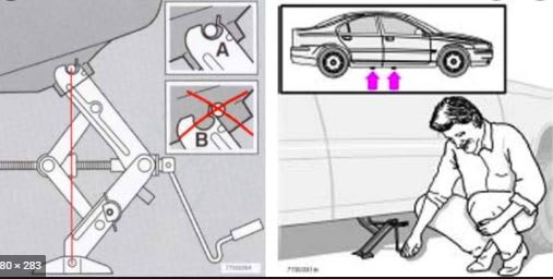
This thing has a single pinned support. What keeps it from rotating counter-clockwise under its own weight until it hits the floor?

============
"Is it the only lesson of history that mankind is unteachable?"
--Winston S. Churchill
 
Friction. There's also a 'foot' on the ground, and the jacking point on the vehicle has a socketty sort of feature.

Cheers

Greg Locock


New here? Try reading these, they might help FAQ731-376
 
podn_vulsbz.jpg


Force in screw depend on angel alfa, Qmax is when alfa=25deg, for alfa>25deg Q=const=Qmax. How can i calculate forces in screw and arms correct ? This structure work as lattice i think.
 
Resolution of forces start with the load Q.

“Do not worry about your problems with mathematics, I assure you mine are far greater.” Albert Einstein
 
PODN1_rwd41n.jpg


This is still bad because i got 2 unkown forces Ra and Rb and 3 equation (x=0 y=0 M=0).
 
Take moments from Ra so Ra*300 sin α = Rb * 150 sin 20°, Transpose and find Rb


“Do not worry about your problems with mathematics, I assure you mine are far greater.” Albert Einstein
 
Add a roller support for stability, draw to scale, calculate a few dimensions and it's a piece of cake. You wouldn't want us to do the calculation for you, would you?

Note that 169/tan25 = 362.4, which I rounded to 362.

image_mbw3mw.png


BA
 
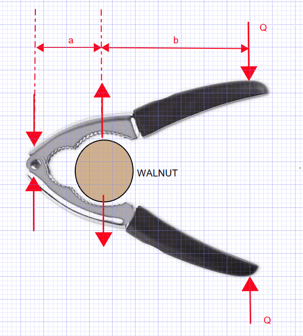
Think of this apparatus as a giant nut cracker where the vertical force Q is applied at the end of each handle. The two handles are joined together by a pin at the roller support. The 'nut' is located 135mm to the right of the left end.

image_yllcew.png


What is the force required to crack the nut? It is a vertical force caused by a beam hinged at the left with a 227mm cantilever and a 135mm back span. Say that force is F. The 'nut' in our case is a diamond shaped frame of length 270mm and height 270*tan25[sup]o[/sup]. Two corners are tied together by a horizontal member to prevent them from spreading.

You should be able to calculate all of the forces using statics.

BA
 
Hey, Agunia, keep us in the loop. Have you solved the problem yet? If not, why not? If Eng-Tips solves it for you, your professor might not take kindly to our interference. I gave you a suggestion; it is up to you to finish it. After you calculate the force acting at the top and bottom of the diamond frame (or walnut), the rest is simple statics. Is there a problem?

I didn't go through your calculation sheet, but at a glance, it appears far too complicated. Let E-T know if we can help.

BA
 
Greg...

Thanks for the explanation. However, is friction in the foot pin enough before engaging the load and is it enough if the load and foot are not precisely aligned? I have only used symmetrical scissor jacks. This type doesn't give me a lot of confidence.

Fred

============
"Is it the only lesson of history that mankind is unteachable?"
--Winston S. Churchill
 
fel3,

I'd say you were correct the first time. The structure is unstable as shown. It needs more support to prevent it from rotating about the bottom pin. That is why I added a roller support at the left end in my model.

Friction should not be relied upon to prevent rotation. The "foot" on the ground can't help because it's below the pin. A socket joint at the top could help, provided the vehicle being jacked is capable of providing adequate lateral support. That is not specifically stated, and should not be relied upon.

I share your lack of confidence in the jack as drawn.

BA
 
Your left hand bottom sketch is unstable, Greg.
The models shown below are much better, although I wouldn't trust any of them on a steep gradient.

image_ane4b0.png


The main difference between your model and these is the fact there are two pins instead of one, above the base plate providing a degree of stability. The assembly could collapse in an orthogonal direction too. For that, there is the width of the base to provide some stability.

image_j8zz78.png


BA
 
GregLocock said:
It is stabilised by the wheels on the other side of the car, although I agree it isn't ideal.

So it relies on the wheels on the other side of the car being locked against rotation. Otherwise, it is not stabilized. I agree it isn't ideal.

BA
 
Status
Not open for further replies.

Part and Inventory Search

Sponsor