Navigation
Install the app
How to install the app on iOS
Follow along with the video below to see how to install our site as a web app on your home screen.
Note: This feature may not be available in some browsers.
More options
Style variation
-
Congratulations TugboatEng on being selected by the Eng-Tips community for having the most helpful posts in the forums last week. Way to Go!
You are using an out of date browser. It may not display this or other websites correctly.
You should upgrade or use an alternative browser.
You should upgrade or use an alternative browser.
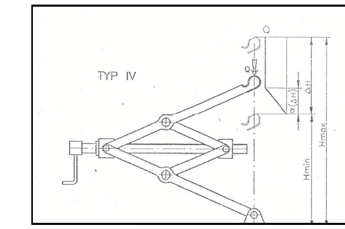
Forces in scissar lift
- Thread starter Agunia
- Start date
- Status
- Not open for further replies.
LionelHutz
Electrical
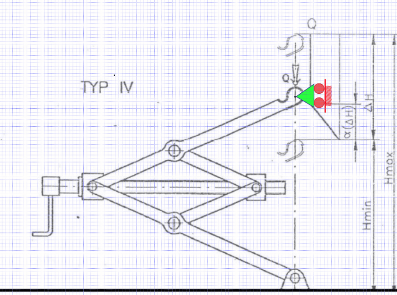
To better represent real-life use, the rolling support should be on the top arm rolling in the vertical direction. Rotate the left support 90* so the arrow points left and put it at the top arm. Still, I don't believe the location used to get it to work in modelling software changes the force calculations in the jack.
To stick as close to reality as possible, the rolling support plane should be an arc so the support moves to the right as the jack is raised. But that still shouldn't change the forces seen by the members in the jack.
To stick as close to reality as possible, the rolling support plane should be an arc so the support moves to the right as the jack is raised. But that still shouldn't change the forces seen by the members in the jack.
BAretired said:So it relies on the wheels on the other side of the car being locked against rotation. Otherwise, it is not stabilized. I agree it isn't ideal.
Even the full scissor jacks you posted rely almost completely on the car being (relatively) rigid and at least two of its wheels remaining in contact with the ground for stability under load. The only real benefit of the stability added by their symmetric design and rectangular base is so you don't have to hold it up with one hand while you try to get it engaged with the car and the ground. In an unconstrained load situation, I wouldn't trust a scissor jack with a cinderblock.
LionelHutz said:To better represent real-life use, the rolling support should be on the top arm rolling in the vertical direction. Rotate the left support 90* so the arrow points left and put it at the top arm. Still, I don't believe the location used to get it to work in modelling software changes the force calculations in the jack.
One extra roller support is needed somewhere to make the structure stable. It carries no load provided the upper pin is directly above the lower pin. It could be in the position shown and, as noted by by LionelHutz, does not change the internal forces or moments in the members.

handleman said:Even the full scissor jacks you posted rely almost completely on the car being (relatively) rigid and at least two of its wheels remaining in contact with the ground for stability under load. The only real benefit of the stability added by their symmetric design and rectangular base is so you don't have to hold it up with one hand while you try to get it engaged with the car and the ground. In an unconstrained load situation, I wouldn't trust a scissor jack with a cinderblock.
Almost completely is not completely, handleman. The full scissor jacks I posted do not rely on wheels remaining in contact with the ground or the rigidity of the car. The applied load could be a sack of mashed potatoes; as long as the centre of gravity of the load remains inside the rectangular base plate, the structure is stable.
However, a slight lateral force could topple the scissor jacks if the resultant of the applied forces lies outside the edge of the base plate. If I were planning to work under the car, I too would want the additional support of some wood blocking or possibly a concrete block (not sure I would trust a cinder block).
The discussion of stability of the structure, while important, was probably not the concern of the OP.
BA
I am a retired structural engineer. What the hell does "external guidance of its load" mean?handleman said:Wait... Are you an engineer or a theoretical physicist? DURING REAL WORLD USE, almost every item described as a "jack" relies entirely on external guidance of its load.
handleman said:The addition of a horizontal roller support in the location you have shown is idiotic.
The vertical roller support I have shown in my latest diagram prevents horizontal movement but permits vertical movement. Nothing idiotic about it.
BA
No "jack" during use is designed to functionally support a load that is not in the direction of its action. A jack acting vertically is totally reliant on outside factors to laterally stabilize the load. It essentially acts as a pinned 2-force member.
Sorry.... Your first roller support was idiotic. Your second is a graphical representation of how this device actually works. I.E. this jack mechanism relies on external guidance of its load.
Sorry.... Your first roller support was idiotic. Your second is a graphical representation of how this device actually works. I.E. this jack mechanism relies on external guidance of its load.
handleman said:No "jack" during use is designed to functionally support a load that is not in the direction of its action. A jack acting vertically is totally reliant on outside factors to laterally stabilize the load. It essentially acts as a pinned 2-force member.
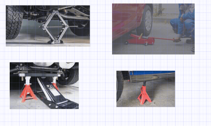
The provision of outside supports to laterally stabilize the load is a wise precaution with any jack, on that we agree. However, the bases in the photos below are not pins, and they do offer some stability, albeit small. They are decidedly better than a pinned base.

handleman said:Sorry.... Your first roller support was idiotic. Your second is a graphical representation of how this device actually works. I.E. this jack mechanism relies on external guidance of its load.
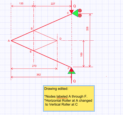
Once again, you are mistaken, handleman. (No, you are not!!) You seem to be batting 1000 today. The horizontal roller in the first diagram is just as effective as the vertical roller in the most recent diagram. In both cases, they prevent rotation of the assembly about the lower pin.
EDIT: The horizontal roller in the first diagram prevents Node A from moving up or down, so it was a mistake.
![[blush] [blush] [blush]](/data/assets/smilies/blush.gif) Following is the corrected diagram.
Following is the corrected diagram. 
Again, while very important to make the structure stable, none of this responds to the OP's question, which addressed forces in the rods, an exercise in elementary statics.
EDIT: My apologies, handleman.
![[blush] [blush] [blush]](/data/assets/smilies/blush.gif) You were right!!! (embarrassed murmuring in background)
You were right!!! (embarrassed murmuring in background)BA
LionelHutz
Electrical
I'm pretty sure the second pin at A would work fine as long as Q is kept pointed towards the bottom pin as the jack is moved.
- Status
- Not open for further replies.
Similar threads
- Question
- Replies
- 0
- Views
- 8K
- Replies
- 5
- Views
- 9K
- Question
- Replies
- 21
- Views
- 22K
- Replies
- 1
- Views
- 467
- Replies
- 9
- Views
- 501

