Eng-Tips is the largest engineering community on the Internet

Intelligent Work Forums for Engineering Professionals

Forces on piping while safety is lifting

Status
Not open for further replies.

pianoman1

Mechanical
Mar 14, 2007
37
0
0
US
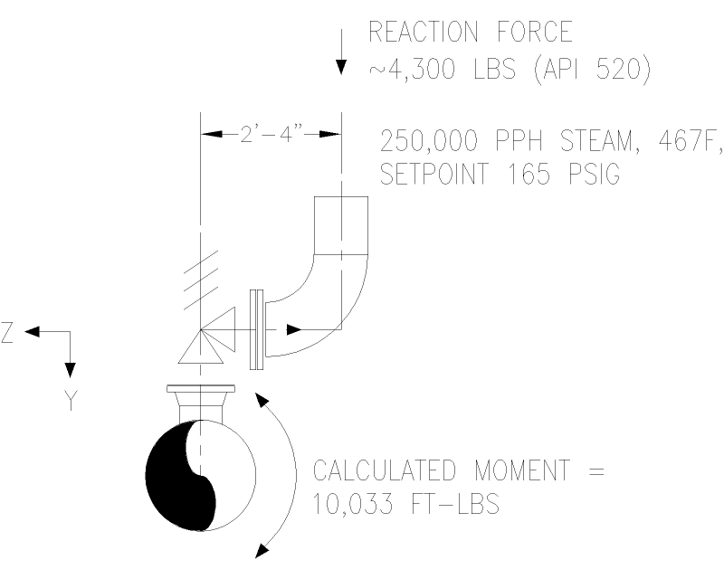
I'm doing some analysis on a 24" steam line, it has an 8T10 safety mounted on top, side exit perpendicular to the pipe run with a 10" elbow turning vertically up and dumping into a 12" drip pan elbow. I calculated the API 520 Part II thrust force, and was just going to apply the moment created by the force x the offset distance (26") to the 24" pipe. But, do I also need to include the actual -Y-direction force on the pipe? I originally thought the moment was all I needed, but intuitively, since the force is close, it seem like it should be included also. If the force were 20 feet away, It would seem insignificant compared to the moment. Basic statics probably, but it's funny after 30 years how you can lose track of a few fundamentals....

Thanks for any feedback.
 
Replies continue below

Recommended for you

I calculated the reactive force at 4250 lbf [18 kN] on this photograph. When I do a force diagram it looks like I would have gotten counter-clockwise rotation without the tail pipe. I think you have to consider every direction.
BentPSV_ejreqz.jpg
.

David Simpson, PE
MuleShoe Engineering

In questions of science, the authority of a thousand is not worth the humble reasoning of a single individual. Galileo Galilei, Italian Physicist
 
zdas04,

Great photo. Sums things up nicely. Was the vessel connection threaded as well, just to adversely compound the situation, or did it just fail the inlet pipe in torsion at the first elbow?

Of all possible ways to put a PSV on a vessel without supporting the outlet, this has to be the worst, in my opinion. One of our clients spun a 2 x 3 "H" out of a vertical separator this way, much like starting up a WW1 airplane propeller. These are the kind of big-picture things I immediately look for when I see a 3-D model or a layout drawing. Presumably, it's safe to assume this wasn't your design.

My simplistic approach would be to compute the reaction force and apply it (1) back against the PSV outlet flange, and (2) downward across the face of the outlet flange and estimate the corresponding moments, which means both directions should be looked at.
 
SNORGY,
LOL, no it wasn't my design. A guy in one of my classes got an e-mail during a break and brought that picture to me chuckling, it had just happened and the foreman wanted advice. Before the break was over, a slide with that photo on it was in my class material.

It is from a company (who necessarily shall remain nameless) that does not allow anything to be threaded anywhere. It looks like all of the deflection was torsional load in the nozzle before the first elbow. The nozzle was Sched 160, and all the flanges are ASME B16.5 Class 600. That tab next to where the PSV used to be had a U-bolt support right under the first flange. It wasn't up to the task.

David Simpson, PE
MuleShoe Engineering

In questions of science, the authority of a thousand is not worth the humble reasoning of a single individual. Galileo Galilei, Italian Physicist
 
Me:

I would look at taking that PSV discharge piping back across the top of the vessel with a stanchion down to a good pipe clamp on the overheads line, before turning upwards. Even then, I'd be looking at the resulting axial load on the top nozzle, because that might not be able to take the reaction forces. I can't see a trunnion near the top of the vessel shell to hang the overheads line from, so my idea might be null and void if there is a spring can somewhere at the bottom. Still, in the absence of conveniently located structural steel, I would be looking at directing the downward force through the vertical centreline of the vessel, provided the top nozzle could take it.
 
Perhaps making up a free body diagram, based on a one end fixen beam, with the other end being unsupported, can help translating the forces and moments back to the main run/PSV Connection.
On the other end, a pipe stress program can do that for you (and also include dynamic effects, which are more difficult with hand calcs). Nevertheless, its always good to have basic hand calc upfront to verify the results that any software spits out.
 
Thank you for the responses. Here's a sketch of the situation. In my stress analysis program I don't have the option to post this as an offset force and let it figure it out, so I need to input both force in the Y-direction and moment. Is it this simple - post the vector forces in the Y and Z directions from the outlet of the elbow and also post the moment in its entirety?

Safety_reaction_forces-Model_ayoeim.png
 
OK, so it's not my best artwork, hastily prepared by a busy guy, you got an intelligent response on the actual content of the question?
 
LOL, Gator, that I why you should always mention what you are referring to. As I said above I got it from a student in one of my classes.

David Simpson, PE
MuleShoe Engineering

In questions of science, the authority of a thousand is not worth the humble reasoning of a single individual. Galileo Galilei, Italian Physicist
 
Now I'm the one laughing, thought Gator was crapping on the sketch. Anyway, I got this figured out, it really is as simple as it looks.
 
At least the problem isn't with Z axis vertical.

Just had of those situations in CII a few days ago...I still hate it...but it was the right thing to do under the circumstances.

I must be missing the humour in this...
 
I think you're missing one more reaction:
Assume
z is vertical (parallel to vessel centerline, either on vessel centerline or at PV wall)
x "north" ("out", directly away from the vessel centerline away down the nozzle centerline.)
Y perpendicular to x, horizontal.

Then, shouldn't the reaction lever arm (total distance acting on the twisted vector) include another term?
Arm = Sq root (x^2 + y^2 + z^2)
 
Status
Not open for further replies.
Back
Top