Continue to Site

Eng-Tips is the largest engineering community on the Internet

Intelligent Work Forums for Engineering Professionals

  • Congratulations KootK on being selected by the Eng-Tips community for having the most helpful posts in the forums last week. Way to Go!

Form 5 (2-element) metering with three(3) wye-connected PTs

Status
Not open for further replies.

LJP1

Electrical
Nov 1, 2018
18
I am replacing a older Form 45S (Elite) meter with a Form 5S (SEL734/5) type meter in a 69kV substation using SEL's recommended Form 5 wiring method.

The application is measuring power on a wye-grounded side of transformer. The meter has two (2) dedicated CTs. There are three (3) PTs (wye-connected primary). The PT secondary circuit is shared with relays (wye-grounded for relays). The relays have their own dedicated sets of three (3) CTs.

My questions are:

Can someone direct me to any representative white papers, or ‘meter man’s bible’ documents that show vector diagrams and wiring sketches for this type of modified Form 5 application. (Note: I cannot 'wrap' CT from other phase).

Setting aside the shared PT circuit at first -
With the PT secondary circuit wired directly to a Form 5 configuration (open delta - with un-metered phase at corner & grounded), will this work (Blondell's Theorem is satisfied)? My concern is that the wye-grounded system could have unbalanced load returning through the neutral.

Shared PT circuit and the need for Aux PTs -
If PT secondary circuit is shared and wired directly to the SEL meter (open delta - with un-metered phase at corner & grounded) does this negatively affect relay and its use of the PT circuit (wye-grounded for relays)?
Or, are two (2) 1:1 Aux PTs for the meter necessary? This would allow for grounding of un-metered phase(now isolated) facing the meter without affecting the relay PT circuit, correct?
With Form 5 application is grounding of the un-metered phase necessary with or without Aux PTs? If not grounded, would Form 5 wiring still negatively impact relays?
If you have dedicated PT secondary wiring for just metering, can you forgo Aux PTs? Or, are they still need for some sort of phase compensation? Is the phase compensation needed for relative consistency/comparison to what the relays are seeing or, does it also affect the power calculations in the meter (SEL claims the Aux PTs and grounding of un-metered/corner phase is not needed)?

 
Replies continue below

Recommended for you

4 wire wye - 1 = 3 elements needed to satisfy Blondel. 2 element metering is for delta and balanced systems.

I don't see why you can't derive two line to line voltages from grounded wye connected VTs. No ground on B phase of course.
 
I'm not following your post...you mention Form 5S 2-element meters, but then you say you have 3 wye-connected VTs.

I'm not a meter form expert, but I understand Form 5S to be a 2-stator/2-element meter, which means that the VTs have to be connected line to line and the secondaries wired in an open delta, assuming you have a 3-wire delta system. But then you say you have a grounded-wye system.


Thanks for the replies.
The meter is on the wye-grounded side of power transformer
CTs are on A & C
Bus PTs provides voltages for A, B & C
PT secondary wired to meter as A-element-B-element-C
Some similar sub meter applications applications have B bonded, some don't.
(For visual reference. See attached PT wiring.)
 
 https://files.engineering.com/getfile.aspx?folder=f4e26f26-cadf-459f-bbaa-8341e8ac3a47&file=PT_wiring.jpg
It looks like three line to neutral PTs to provide an open delta equivalent line to line voltage to the two potential elements of the meter.
Is that correct?
As I understand metering, that will not accurately meter unbalanced loads and may have issues if your line to neutral voltages are not of equal magnitude and/or phase angles.
The metering will be accurate for balanced currents and unbalanced voltages, but not for balanced voltages and unbalanced currents.
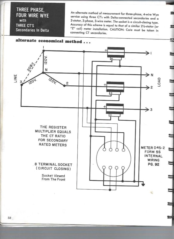
I have successfully metered unbalanced loads with a two element meter and three CTs in delta.
The ratio of the meter impedance to the CT impedance is so very high that virtually all of the CT secondary current flows through the meter elements rather than through the other CT secondaries.
If C phase is the odd phase, the A phase element meters the A phase component of C phase and the B phase element meters the B phase component.
The meter assumes that the C phase voltage is the weighted average of the A phase and B phase voltages.
At unity power factor the weighing is 50:50. As the power factor drops the weighing shifts, but as this solution is only used with well balanced voltages there is no overall effect.
We used this metering for a number of years.
Then we lost one phase of an undersea twisted triplex cable. The repair consisted of a single conductor cable laid about 2 or 3 feet away from the original cable to carry the lost phase. The undersea length was about 1000 feet.
This gave us a voltage drop on one phase that rendered our metering accuracy unacceptable. We converted to three element metering after that.

Bill
--------------------
"Why not the best?"
Jimmy Carter
 
The meter won't care the B phase is ungrounded. The relays shouldn't care the meter is connected line to line, due to its high impedance. Why not fix this thing while you're at it and go three element. Hope it's not for revenue. What's the nature of the load monitored?
 
Impedance of meters and relays:
Potential elements high impedance.
Current elements low impedance.

Bill
--------------------
"Why not the best?"
Jimmy Carter
 
I have admitted bias (working for instrument transformer manufacturer) but I don't understand why 3 CTs wouldn't have been used here from the beginning. If the metering is for revenue then you really should add a CT and use a 3 element 9S meter.
 
I agree with scottf. Although I have successfully used a two element solution at the time I was at a remote island system with very little money and very long and slow supply lines. I solved the metering problem with the equipment that was available.
I doubt that I will ever again use the two element solution.
However if you are constrained to using existing equipment as I was, the delta CT solution will work with the accuracy dependent on the voltages being equal.

Bill
--------------------
"Why not the best?"
Jimmy Carter
 
1) Added another representative diagram. (Note: for simplicity the CTs are not shown but there are two (2) dedicated CTs for phases A and C to the meter.)
With the SEL73X meter setup as Form 5, it is believed that we need Aux PTs to shift the voltage angles to line up and work with the Form 5 calcs inside the meter.
Anyone with experience with SEL meters and/or this setup?

2) The meter IS used for revenue/LBA purposes. Recognizing, that the 2-element would be inaccurate for increasingly unbalanced load, I am wondering what true risk there is at higher transmission levels with strong source(s) and where the lower voltage lines leaving sub are delta. With that said, small percentage errors at transmission levels can add up to real/big lost $'s annually. I just don't know how to prove inaccuracies to justify the purchase of a 3rd CTs for retrofit projects. I am think I should go to a sub with 3 set instruments and setup a 2nd Form 5 meter to compare to the installed Form 9.
 
 https://files.engineering.com/getfile.aspx?folder=ca96e217-0d84-4c81-a051-712897aa94d7&file=2-Element_Metering_with_Shared_Wye_PTs_&_with_Aux_PTs_2.pdf
Link is broken.

A delta-delta connection provides no phase shift. A wye-wye connection likewise has no phase shift. Vab is in the same direction whether it is derived from one line to line connected VT or two line to neutral connected VTs. You will need to watch your multiplier, though.

Do I understand the loads you are metering are on the lower voltage delta lines?
 
Here is the two element, delta CT metering scheme from my old Westinghouse Metering Book. This scheme assumes that the voltages are equal.
two_element_metering_pfrnwn.jpg

This scheme worked well for us for a number of years but I would rather use a three element meter. It doesn't take long for even a small metering error to exceed the cost of a three element solution.
Bill
--------------------
"Why not the best?"
Jimmy Carter
 
stevenal,
Sorry for the bad link. Attached is another try as a JPEG. Hopefully it works this time.
Again, just for simplicity of diagram, the two (2) metering CTs are not shown but they are on 161kV Phase A & C.

 
 https://files.engineering.com/getfile.aspx?folder=2ab3a471-d4b3-4b63-bf27-2e7c19638707&file=IPL_2-Element_Metering_with_Shared_PTs.jpg
At 161kV, the possible lost/inaccurate revenue from such a scheme due to unbalanced loads/voltages seems to easily justify adding an additional CT...either free-standing or slip-over CT on the power transformer.

Have you looked at the existing CT's ratio versus actual load current levels? Often times HV CTs are over-sized. You might find that adding 3 correctly sized slip-over CTs would be more cost-effective than adding an additional 161kV CT.

 
Link works now.

All your auxiliary PTs are accomplishing is providing isolation so you can ground Vb. They are providing no phase shift, and none is needed.

Instrument transformer circuits are grounded so they do not float to high potentials. Corner grounding an open delta PT
accomplishes this, but so does grounding the wye point of wye PTs. Eliminate the auxiliary PT, wire straight through, and unground Vb.

Instead of trying to fix a problem that doesn't exist on the potential side, I would look into fixing the inaccurate metering issue caused by too few current transformers.

My question above remains unanswered. What direction(s) is(are) the energy flow(s) through this system?
 
stevenal, Thanks for the response. While I agree with you about not needing the aux PTs, I am still trying to get two (2) internal parties to concur with this assessment. I wish I were more effective at overlaying the vectors on this diagram to prove the point.

Regarding the CTs and flow... Most all of the locations where I am facing retrofitting the metering have Wye-G system with two(2)issue also have multiple circuits and buses/voltages with a tie meter(s) for only some of the circuits that connect to another LBA/utility. Typically we are metering the flow at 161kV or 69kV and, depending on the season and loading the flow direction may change. I know there is the risk of metering error with two (2) CTs however I am having a difficult time proving the magnitude of the financial risk to my management. As I mentioned earlier, at higher system voltages and stronger source(s), I believe the dollar risk is greater but the likelihood for unbalanced load that would cause the error might be less. So, how can a build a business case for 3-element metering as a definitive solution to avoid the 'potential' risk. What is peace of mind worth...
 
LJP1-

Do you have the load metering data available so you can see what the current magnitudes are and then check those against the installed CT ratios? It might be easier for you to build a case for CT replacement/correction than to prove the error introduced by 2-element metering.

Also, can you get current level info from other CTs in the power transformer that might be feeding relays? Seems you could gather data somewhat easily to see how balanced it is.


Scottf,

I am working on anglicizing that data; unfortunately the existing legacy meter installation does not provide real-time SCADA Amps or MW values (the MW are read by separate transducer, also 2-element) values. I have only done a snap shot of relay amps & MW at the same time as meter amps, which show about a 2-3% error.

We also compare meter KYZ counts in SCADA to the integrated 3-phase MW values over the same time period (from another source - line relay). For some sites 2-element meter sites, we don't see a significant difference. At other sites we see ~1-2% difference. Compounding the uncertainty in all of this analysis is relay CT and meter CT have different % accuracy ratings, which is the same magnitude as the potential error.
 
Depending on the current level versus the ratio of the relay class CTs, the error should be substantially different than metering class CTs. For example, a CT rated C800 will certainly meet a 0.3B1.8 meter rating. However, if you are operating below the 10%Inom point, you may see the accuracy fall off faster for a relay class CT versus a metering class CT.

To me, comparing readings from metering class CTs to relay class CTs is the least of your problems :)

 
Is it feasible to monitor or meter the neutral current? That will give an indication of the amount of unbalanced current.
Your metering may be high or low.
If your circuit is well balanced then the meter's assumption that "the current in the unmetered phase is equal to the average of the currents in the metered phases" may be correct.


Bill
--------------------
"Why not the best?"
Jimmy Carter
 
Status
Not open for further replies.

Part and Inventory Search

Sponsor