Continue to Site

Eng-Tips is the largest engineering community on the Internet

Intelligent Work Forums for Engineering Professionals

  • Congratulations SDETERS on being selected by the Eng-Tips community for having the most helpful posts in the forums last week. Way to Go!

Form error in the stackup calculation 3

Status
Not open for further replies.

gabimo

Mechanical
May 2, 2013
124
Calculate the minimum wall thickness


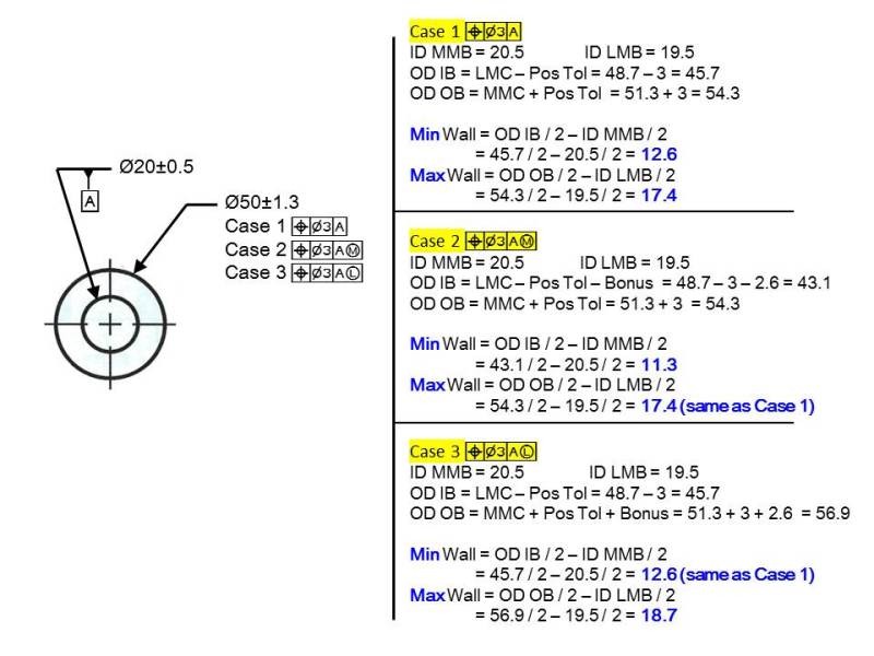
When both features (considered features and datum feature) are at RFS, do we need to include both form errors in the stackup calculation?
Cylindrical part with a thru hole

Dimensions in mm

ID: 20 ± 0.5—datum feature A
OD: 50 ±1.3, position Ø3 (RFS) to A (RFS)
What is the minimum wall thickness:
Form error on A: 2x 0.5 = 1mm
Form error on OD: 2x 1.3 = 2.6mm

X max, x minimum,
 
Replies continue below

Recommended for you

gabimot,

Minimum wall thickness is 10.8, and form error is involved for both features. It determines how far the actual surfaces can deviate from the unrelated actual mating envelopes. Such deviation decreases wall thickness.

Maximum wall thickness is 17.4, and form error is not involved for either feature.


pylfrm
 
Max is 17.4
Min is 12.6

Form tolerance is directly from the size tolerance in your example, so I'm not sure why it would be of concern.

John-Paul Belanger
Certified Sr. GD&T Professional
Geometric Learning Systems
 
I got “almost” the same values.

X max: 17.4 (same value as everyone)
X min: 12.1. I am not sure why I am missing another 1.3.
X min:
-20.5/2 = -10.25
+48.70/2 = +24.35
Ø3 / 2 = -1.5

Total: 24.35-10.25-1.5 = 12.6
12.6- form error on datum feature A (0.5) = 12.1 (I am working on the radius, so everything is divided by 2)

Pylfrm and everyone,

Just for my own education, how the requested values (X max and x min), would change, if datum feature A would be called at MMC/MMB or LMC/LMB?
Adjusted case 1 OD: 50 ±1.3, position Ø3 (RFS) to A (MMC/MMB)
Adjusted case 2 OD: 50 ±1.3, position Ø3 (RFS) to A (LMC/LMB)

I really appreciate your contribution here on the forum and the amount of education you provided. “Datum shift” thread was another excellent example. At least for me was an outstanding piece of “training material”
 
For my adjusted scenarios I got:
Adjusted case 1 OD: 50 ±1.3, position Ø3 (RFS) to A (MMC/MMB)
X max: 17.4
x min: 12.1

Adjusted case 2 OD: 50 ±1.3, position Ø3 (RFS) to A (LMC/LMB)
X max: 17.9
x min: 12.6

Am I correct?
 
Nescius,
I reconcile the x min value. Should be 10.8.

Also, do you agree with the values for the "adjusted cases":

Adjusted case 1 OD: 50 ±1.3, position Ø3 (RFS) to A (MMC/MMB)
X max: 17.4
x min: 12.1

Adjusted case 2 OD: 50 ±1.3, position Ø3 (RFS) to A (LMC/LMB)
X max: 17.9
x min: 12.6
 
I calculate:

10.8 min/17.4 max when A is modified at MMB
11.3 min/17.9 max when A is modified at LMB
 
Nescius said:
10.8 min/17.4 max when A is modified at MMB
11.3 min/17.9 max when A is modified at LMB

I agree.


pylfrm
 
Okay, so looks like I have a problem (of understanding) how to calculate the minimum wall when the considered feature is RFS. (for the maximum wall I guess I am fine, even the considered feature is RFS).
My brain just does not get it. (along with the issue raised on VC/ RC thread earlier this week)

Adjusted case 1 OD: 50 ±1.3, position Ø3 (RFS) to A (MMC/MMB)
X max: 17.4
x min: 12.1 (should be 10.8)

Adjusted case 2 OD: 50 ±1.3, position Ø3 (RFS) to A (LMC/LMB)
X max: 17.9
x min: 12.6 (should be 11.3)

Now, the question is why?
Why, I have to subtract another 1.3 from the min wall ?
First of all, everyone agrees with these numbers?
 
greenimi,

The drawing posted by Nescius shows the minimum wall condition for both the original RMB case, and for your modified MMB case.

For your modified LMB case, the minimum wall condition could look the same except with a perfectly cylindrical datum feature having diameter 20.5.

Once you have drawn or imagined the geometry that results in the desired extreme value, the correct numbers should fall right out. Trying find and remember a calculation method that skips this step doesn't seem very useful to me.


pylfrm
 
Thank you pylfrm,

As I said it before: you can explain it to me, but you cannot understand it for me.

Also, a big thank you to Nescius for the sketch provided earlier.

I will get it..hopefully. I am not at your, Nescius or pmarc's level yet, but I am working on it..... [wink]
 
Ha! I'm not sure you'd want to be at my level. [bigsmile] I am nowhere near as experienced as the famous names in this sub forum. Having Solidworks at my disposal helps me tremendously.
What pylfrm said above is key:

"...how far the actual surfaces can deviate from the unrelated actual mating envelopes."

Spoken more broadly, the way GD&T "touches" a part is not necessarily the same way other components in an assembly may "touch" the part. In the case of a planar datum feature, a simulator touches the highest points, where a mating part might not touch those points at all due to form errors.

 
Nescius said:
11.3 min/17.9 max when A is modified at LMB

These numbers are true for LMB size of datum feature A = 20.5.

My qustion would be: Is the LMB size really 20.5?
 
pmarc said:
Nescius said:
11.3 min/17.9 max when A is modified at LMB

These numbers are true for LMB size of datum feature A = 20.5.

My qustion would be: Is the LMB size really 20.5?

Good point. I guess the LMB size is actually 21.5, which would make the answer 10.8 min / 18.4 max. Right?

pylfrm
 
Dang. Position tolerance at LMC requires perfect form at LMC. I don't know why my brain assumed perfect form when a datum feature is referenced at LMB.
 
pylfrm said:
Good point. I guess the LMB size is actually 21.5, which would make the answer 10.8 min / 18.4 max. Right?

Right, Sir.
 
Where 18.4 max is coming from?
I guess I got 10.8 min for A(LMB)

Are 10.8 and 17.4 for A(MMB) the correct answers?
 
I know I am “abusing and bullying” pmarc and the rest of the quiet members of this forum, but I like to confirm the values below, and especially the ones where the datum features is called at LMB.
Does anyone have any books where these "KIND" of calculations are explained in details? Kurlikovski tolerance stackup does not have the form error included.

ID: 20 ± 0.5—datum feature A

What is the minimum wall thickness:

Adjusted case 1 OD: 50 ±1.3, position Ø3 (RFS) to A (MMC/MMB)
X max: 17.4
x min: 12.1 (should be 10.8)

Adjusted case 2 OD: 50 ±1.3, position Ø3 (RFS) to A (LMC/LMB)
X max: 17.9, (should be 18.4)
x min: 12.6 (should be 11.3) (should be 10.8)
 
Here is my calculation, please let me know if I am wrong.

Season
Max_Min_wall_m8crjt.jpg
 
Status
Not open for further replies.

Part and Inventory Search

Sponsor