Continue to Site

Eng-Tips is the largest engineering community on the Internet

Intelligent Work Forums for Engineering Professionals

  • Congratulations MintJulep on being selected by the Eng-Tips community for having the most helpful posts in the forums last week. Way to Go!

Foundation for PEMB with Heavy Moment and Uplift Reactions

Status
Not open for further replies.

ajdg29

Structural
Sep 10, 2015
14
I am currently working on foundation design for a PEMB in Texas. There are three frames that have heavy moment reactions along with the reactions in the X & Y planes. This moment is roughly 2,500k-ft when looking at ASD load combinations for 2009IBC. Shear is roughly 80k, maximum downward load is 276k and uplift is 200k.

My question is what is typically done for a situation like this. As of right now, I was planning on extending the leg/base plate and providing a buried pad footing to support the vertical load, with a deep grade beam running over the top to take out the moment. I would weld rebar to the column to take out the force couple cause by the moment into the grade beam.

Is this this best way? The PEMB engineer said they typically just provide a connection to the finished floor level. The base plate they are providing at these connections are built up and are about 5'-6" wide between bolts to take out the moment with the 1-3/4" diameter 105ksi bolts. I'm just not sure that is the best way to resolve the high loads. Any direction would be appreciated. Thanks.
 
 http://files.engineering.com/getfile.aspx?folder=f5ef3a80-f918-478d-a958-6580555a12dd&file=BOOT.PDF
Replies continue below

Recommended for you

Perhaps the PEMB engineer needs more mainframe lines to lessen the reactions. Is this in a high wind area? Seismic should not control for a PEMB unless it is supporting concrete tilt up walls.

Mike McCann, PE, SE (WA)


Wind speed is 100mph ASD (2009 IBC). Seismic Sds = 0.099. The moments are due to wind per the loading sheet I attached a few posts up.
 
Designing rigid frames for 125' spans involves some tradeoffs. You can save a lot of steel by providing fixity at the base, but with extra cost in the footings. I haven't done "PEMB" building footings for buildings of this magnitude, but purposely designed industrial buildings, particularly with cranes, often have heavy bases like this and deep footings.
 
So maybe design a grade beam as a deep concrete beam to transfer the moment to deep piles to resolve the force couple?
 
Or have the PEMB pin the base... Now there's a thought...

Mike McCann, PE, SE (WA)


Yes, but the 200k uplift will still require a huge foundation to resolve, so pinning the base may not have a large effect as hoped.
 
ajdf29, refer back to the article jeffandmike linked above. Fixing the base makes the building cheaper for the metal building manufacturer, but makes the foundation cost go up significantly, as you're experiencing. FWIW, I would send this back and make them pin the base and add in more bents if necessary.
 
When the engineer doesn't have complete control of the structural design, this sort of thing happens. We don't know much about the use of this building, or how it is being contracted. If the PEMB manufacturer has just been contracted to provide a building to cover space, and this is the most economical design to meet the criteria, then the footing designer is stuck with dealing with it.

There are some serviceability stiffness advantages to providing fixity in the base, so I wouldn't dismiss this as a poor design without a lot more information.
 
Did you tell the owner that the PEMB manufacturer is costing him a ton of money in concrete with his design? If not, I would not go too deep into this design beyond some prelim calcs to get a magnitude of the foundation that one might need. The owner is bound to ask how much. This is a case of a supplier robbing Peter to pay Paul. I would expect that adding a few tons of steel would be far more cost effective than trying to deal with those base forces.
 
I believe it is unrealistic to expect a rigid response of a fdn for such a large moment unless one goes to extreme lengths(mat fdn) to resist it...it does not take much rotation of the fdn to transfer this moment back into the steel frames which are not designed to handle it.....as others suggested, the optimum solution is the have them design the steel frames to take this moment and have pinned bases......it looks like the specs for these PEMBs should be tightened up to require the PEMB suppliers to design the steel frames to have pinned bases.
 
I totally agree with: You PEMB guys might think it's all clever to take no responsibility for the "blob of concrete" but the people who do, like me, are passing the word that a) it's not reasonable and b) you're not meeting us halfway by not giving us reasonable loads, load combinations, bolt spacings or edge distances. And the people who pay for these are noticing.
As far as the loads that ajdg29 is trying to design for, as others have said, they look incorrect. I'd request the calculations and see if you can recreate them. One thing to do in the future is to specify that all supports to be pinned at the base.
 
A lot of people wanting pinned bases without much information on the building, except that the frames span 125'. We don't even know how high the building is, or much about the applied loads. But if the distance between the bolts is 5'-6", the column is big, maybe 60" deep. (Sorry, on rereading, the building is 82' high at the knee). Not your everyday PEMB, I would have thought.
 
82' high and 125' span on 3000 psf soil. I see a deep foundation system in the owners future.

 
Ok, going back over the reactions given in what I posted earlier (18:29), using the correct signage, I get the maximum moment using ASD combination 16-14 (0.6D+W) as 1893k-ft. Still, this is a huge moment to account for, and I'm coming up with a grade beam of 7'W x 5'D x 35'L to meet the allowable bearing pressure of 3,990PSF.
 
What about a shorter gradebeam that is supported on deep foundations. Turning the moment into axial forces (both up and down).
 
This will be a little off topic but what the hey. When I look at your frame geometry and the supplied reactions, a couple of things jump out at me:

1) Gravity loads contribute a good deal to the reactions and;

2) I suspect that the reason for pursuing base fixity was to limit a) midspan roof deflection and b) lateral wind drift.

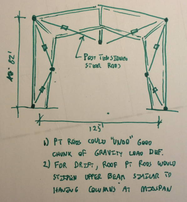
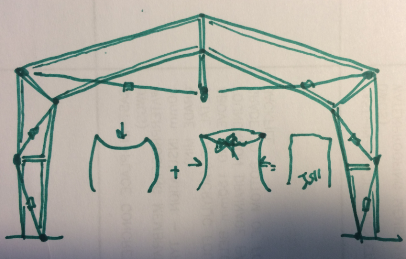
If you could talk your PEMB supplier into a little adventure, I wonder if post-tensioning the frame might be an elegant improvement here. While exotic looking, in this instance, post-tensioning would simply involve some extra, routine hardware and a couple of extra installation steps. There would be cost involved but, perhaps, less cost than some of the rather extreme foundation solutions that we've been contemplating.

As I see it, post-tensioning would have the following advantages:

1) You could essentially undo much of the gravity load deformations. This would be similar to load balancing in PT concrete.

2) You could stiffen the frame against lateral drift by making the rafter assembly stiffer. It would be closer to the stiffness that one would expect with a center line of columns.

Capture01_ta0iop.png


I like to debate structural engineering theory -- a lot. If I challenge you on something, know that I'm doing so because I respect your opinion enough to either change it or adopt it.
 
Just realized that I've got my PT rods in backwards in the columns. Please think of them mirrored about a vertical axis.

I like to debate structural engineering theory -- a lot. If I challenge you on something, know that I'm doing so because I respect your opinion enough to either change it or adopt it.
 
More gooder.

Capture01_hmgtym.png


I like to debate structural engineering theory -- a lot. If I challenge you on something, know that I'm doing so because I respect your opinion enough to either change it or adopt it.
 
Status
Not open for further replies.

Part and Inventory Search

Sponsor