Continue to Site

Eng-Tips is the largest engineering community on the Internet

Intelligent Work Forums for Engineering Professionals

  • Congratulations KootK on being selected by the Eng-Tips community for having the most helpful posts in the forums last week. Way to Go!

Foundation sizes for short retaining walls 1

Status
Not open for further replies.

bnickeson

Structural
Apr 7, 2009
77
Hello all, I'm dealing with a design issue that crops up numerous times each year and I'm curious on your opinions. We have a situation where a load-bearing building perimeter stem wall needs to act as a cantilevered retaining wall and laterally resist about 18" of net exterior grade difference. That's it. Just a very short wall to retain a little soil. The problem with this is that the analysis for foundation widths when designing retaining walls only takes into account the overturning moment of the soil versus the resisting moments of the footing and any dead loads on the wall. It does not include any passive pressures against the foundation. In our area of the country, we use 3'-0" deep grade beams for pretty much everything, so the lateral soil pressure acts against 3'-0" of grade beam plus a 2'-0" retaining wall. The footing size you get for this is over 3'-6" wide in my case, which seems completely ridiculous for retaining 18" of net soil.

To illustrate the ridiculousness of standard retaining wall analysis on a short wall (using Retain Pro in this case), if the top of soil on one side of a wall was 100'-1" and the height of soil on the opposite side was 100'-0", it would require a 2'-4" wide footing. Obviously that is not realistic.

For these types of short walls where you have significantly more depth of foundation than net height of retaining soil, do you analyze them differently? Do you just look at the lateral soil pressure on the wall above the footing? Or allow the passive pressure against the footing to act as a resisting moment? I'm afraid the architect or contractor will kill me for putting in a 3'-8" footing for retaining 18" of soil.

Thanks.
 
Replies continue below

Recommended for you

If you truly cannot use the passive pressure on the other side against the 3' grade beam, then you do have a 4.5' to 5' retaining wall and the size isn't unrealistic. If you can tie the slab on grade into the wall then you have a restrained wall and only need to deal with the "kick out" effect at the base of the footing (sliding) which would yield a smaller foundation.

Your comment about RetainPro, I suggest you look at your inputs as I suspect you are not dealing with 1" retaining and are not accounting for the soils on the opposite side resisting overturning. I have used the software many times for freestanding walls with equal soil on each side and never had such a crazy footing due to soil loadin gonly unless the inputs were wrong.

Short answer, if you cannot rely on the soil on the opposite side, then you have a deeper retaining scenario and the footing makes sense, if you can utilize the soils on the opposite side, then update your inputs into the software and get a smaller footing.
 
Your practice of using a 3'-0" deep grade beam seems to be one source of your problem. And to add a 2'-0" retaining wall on top makes it a 5'-0" deep beam.

It's a load bearing wall, so your footing has to be below frost depth. How deep is that? Why not reduce the grade beam to a dimension which satisfies frost depth requirements? If you have a grade slab butting up to the wall, dowel it to the slab.

If a 2'-0" wide footing is adequate as a bearing wall, I would use a strip footing 8" deep by 24" wide, centered under the wall. I prefer dowels to the slab to retain the 18" soil differential. Relying on passive pressure does not seem to be a good idea.
 
Aesur, as far as I can tell, there is no input toggle in Retain Pro to use the passive soil resistance to resist overturning. So in essence, that soil only exists for sliding resistance and does not exist for overturning within the program. That's my whole beef with it.

As as far as your last comment, I *should* be able to rely on the soil on the opposite side of the grade beam. However, I am not aware of any retaining wall design methodology that includes this. That makes sense for taller walls, but it is not rational for short walls like this where there is barely any unbalanced soil load.

BAretired, the depth of the grade beam is due to frost (it's 42" here). We cannot change that. And doweling into a slab-on-grade isn't practical as the slab is often poured months after the wall is constructed and the soil is backfilled. Not to mention tons of dowels through the wall forms are expensive and labor intensive.

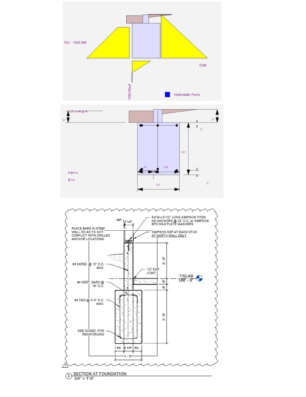
See the attached image for a couple screen shots from Retain Pro showing the automatic footing design for a wall retaining 1" of net soil and my detail of the retaining wall so we're on the same page.

Retaining_wall_l9tegn.jpg
 
You must have some crazy high active pressures to get 724 plf at the base. When I run your example above with local soil conditions, I get 257 plf and a 1'-2" wide footing if I use 36" depth.
 
Yes, it's 103 plf undrained active. I already talked to the geotech about it because I thought it was a misprint. It's like 40% higher than the highest value I've ever seen.
 
I agree this is dumb.
You can do this by inspection - so be done. The heck with using software

I tried using RP once and thought the interface was so terrible that I returned it.
 
bnickeson said:
Yes, it's 103 plf undrained active.
I believe you have found the problem. I have never seen over 45 pcf active.
 
Too bad Section 3 wasn't in the OP. I thought the high ground was on the inside. In that case, dowels would be needed. But the high ground is on the outside, so the wall can bear against the slab...no dowels required. All you need do is design the vertical bars for the small moment from 24" fill above top of grade beam. The beam can't rotate outward if backfill has been placed.

The image from Retain Pro is not consistent with Section 3, and does not accurately depict the behavior of the retaining wall.

 
The problem is that you are trying to use software to design something that the software wasn't optimized for. Sometimes you just have to stop and think about what you're looking at instead of trying to force it to work through a black box.

This is a simple hand calculation. You are looking at a single vertical element: The 3-ft grade beam below the slab plus the 2-ft wall above slab, all working together. The vertical element can pivot around the slab (assume pinned), which resists the entire horizontal load. I'd add reinforcing and/or thickness to the slab to resist this load, but with only 2-ft of imbalance this is overkill. Mainly I'd add it so the contractor has to pay attention to the slab in this location and won't cut corners here.

Ignore the passive pressure on the interior side of the grade beam (the slab is stiffer, so it will carry the load instead of the soil). Balance is achieved by only looking at pressures on the exterior side. You have active at rest pressure above the slab trying to rotate the wall one way. You have passive pressures below the slab trying to hold it in place. Without even picking up my calculator I can guarantee that passive pressure below the slab on the 3-ft grade beam is higher than the active at rest pressure on the 2-ft wall, so it's balanced and stable. No need for a standard cantilever retaining wall horizontal element to resist overturning.

Design the vertical reinforcing in the wall to handle the active pressure moment, extend it all the way into the footing for development, and you're done.

Theoretically you could make the grade beam much smaller because the raised grade eliminates frost depth problems, but I wouldn't do this. They could lower the grade in the future.

Edit: Changed "active" to "at rest". The wall is fully restrained and won't be able to rotate enough to develop the reduction to active pressure.
 
Thanks for the replies everyone, but this question was more theoretical in nature and not exactly limited to this one case I have. Yes, there is an interior slab in this case, but it may not be poured for months after the wall is backfilled and on future cases there may not be a slab at all. The question pertained mostly to the design of short retaining walls with very little net soil difference regardless of what the active pressure is. If this were an exterior retaining wall far from a building with no slabs adjacent to it, what would your design procedure be? Would you use software to tell you that you need a 2'-6" plus wide footing to retain something like 12" of soil? Or, as XR250 suggested, would you ignore that and realize that the footing can't rotate within the soil with impunity and is fine by inspection?

I just manually tried a method in which the passive pressure could act as a resisting moment and - for the 2' tall stem wall case above ignoring the slab - got a 3'-0" footing to work. It's still quite large but better than what a classical analysis would give. I suppose you could also try only analyzing the active pressure from the soil above the soil on the opposite side, but that might be a bit too unconservative for my taste.
 
I wouldn't ignore it - had a renovation in construction recently that, when old finishes were stripped off, the foundation wall that cantilevered up 16" above exterior grade and backfilled with a floating slab was deflecting a solid 2 inches in places - but I also wouldn't worry too much about it.

You should absolutely consider passive resistance on the low side. Now, if you're looking at 12" or less above the footing on the low side, ignore that because it'll be loose and mostly top soil. But if you're deeper, then make sure you specify structural backfill with appropriate compaction. The deeper you go, the less restraining moment will need to come from eccentric load on the footing, and the smaller it can be.
 
For the condition shown on Section 3, jwkilgore nailed it! The slab takes the load and the bottom of the grade beam exerts pressure outward against the soil, not as shown on your RP output.

bnickeson said:
If this were an exterior retaining wall far from a building with no slabs adjacent to it, what would your design procedure be?

That would make it a completely different case and should be recognized as such. There would be no slab to resist movement in the wall. In my area, the frost depth adjacent to a heated building is said to be four or five feet. In a wide open field, it is more like six to eight feet. Consequently, for the typical clay soil in my area, I do not always take the retaining wall footing down below frost depth, but I would take it down far enough to develop enough passive pressure to resist the active pressure on the opposite side. I would expect frost heave to be uniform along the wall, unless there was reason to expect otherwise.

Each case is different and the designer must bear that in mind.
 
Also keep in mind that, in these cases, at rest pressure may be more appropriate as some deflection of the wall outward is necessary for the pressure to drop to active levels. That may not be appropriate with a wall sitting top.
 
Those active and passive triangles look all wrong. Passive coefficient is normally 5-10x the active.
Code:
 
From your detail you have an exterior wall built on top of the stem for these cases I prefer to use at-rest pressure for the de-stabilizing and stabilizing pressures.

You mentioned not seeing a method to use soil pressure to resist overturning thats really just statics and applying the appropriate load combinations.

For your detail you need to do a free body considering:
De-stabilizing soil
Stabilizing soil ( this receives a reduced load factor per IBC and ASCE load combinations, as well as a rational judgment on how much soil to use for permanent resistance)
Vertical load in the wall above
Self weight of the stem
Self weight of the grade beam
Wind pressure wall reaction on the top of the stem
Wind pressure on the stem
Seismic reaction at the top of the stem
Any surcharge on the de-stabilizing side
Any surcharge on the stabilizing side
Etc.

If you really need to sharpen the pencil soil weight on top of the grade beam projections.

Then the analysis is a statics exercise of:
Sum Fx = 0
Sum Fy = 0
Sum Mz = 0, where z is an axis out of page choosing any convenient point to sum moments about.

Also remember that to generate the full passive pressure requires significant movement into the resisting soil side (you start at-rest and build up to the passive amount). Most geotechnical books have a little chart that shows movement ratios away and into soil illustrating either active or passive pressure development.

Retain pro in my experience is a poor choice for things like this as your extremely limited to only the conditions built into the program so won’t be able to capture some of the load conditions your stem wall will experience.

You would be doing yourself a huge favor working through full detailed hand calculations and perhaps in tandem developing an excel sheet that covers all the load conditions and load combinations required by IBC/ASCE. Note that there are stability combos defined in the foundation chapter of IBC. (Mean do this calc soup to nuts all the way down to the stem bar development lengths into the beam and the wall anchorage to the stem)
 
BA said:
The slab takes the load and the bottom of the grade beam exerts pressure outward against the soil, not as shown on your RP output.

I love how we all assume a slab is going to brace a stem or basement wall.
I regularly see 1/8" to 1/4" gaps between the slab and the wall and add in the expansion joint material and you ain't got bracing until the thing starts to lean.

Thank the contractor who added a shit-ton of water to the mix because it was 100 degrees out.
 
Some lateral movement does occur. Retaining wall design is not an exact science!
 
Yes some movement is going to happen unless you design a very rigid wall. I think XR250’s point is that too much rotation might need to occur to achieve the “pin” assumption, unless provisions are made to close the gap to begin with. In the original detail here there is a 1/2” gap at the slab. That can translate to a very big lean at the top of the wall.

Of course, this wall is embedded 3 feet, so isn’t going to move much. The passive pressure will stop it pretty quick.
 
I have never seen a 1/2" expansion joint between slab and wall, and I admit that I missed that note on Section 3. Normally, in my experience, the joint between slab and wall consists of 3/8" AIFB (Asphalt Impregnated Fiberboard). There will still be some movement because the fiberboard compresses slightly when loaded.

Leaving a 1/2" clear gap between slab and wall allows water to infiltrate, which is not only a bad idea, but difficult to achieve. Hence, it is never done.
 
Status
Not open for further replies.

Part and Inventory Search

Sponsor