Continue to Site

Eng-Tips is the largest engineering community on the Internet

Intelligent Work Forums for Engineering Professionals

  • Congratulations waross on being selected by the Eng-Tips community for having the most helpful posts in the forums last week. Way to Go!

Frame calculation. How to?

Status
Not open for further replies.

Josv

Mechanical
Jan 13, 2021
4
Hello,

Last Octobre I graduated and received my associate degree in mechanical engineering. Since then I'm working for a company which designs food processing machines. Since the beginning I'm struggling with some engineering tasks, mainly the calculation of frames. In my study I learned the basics about statics, mostly simple beams etc. When I have to calculate simple beams and determine the internal forces and stresses I'm doing just fine. Also pinned frame connections I get. I asked my fellow engineers at work how they calculate and design frames. Their answer is: experience!. This is an answer that does not satisfy my needs. I want to understand what I'm doing and I want to analyze my frame design. I want to know where are the most important stresses and how can I improve my design. I want to be able to hand calculate my frames and based of these hand calculation make a decision.

I was wondering if some of you guys have some tips for me? I have made a simple design in Inventor of a frame with a "machine" on it. I was wondering how you guys would attack this problem and how to hand calculate this issue so that you can see where the biggest stresses are? I have tried do dismember the frame just like a pinned frame, but that leaves me with to many unknowns (maybe use compatibility equations???). It's a welded frame, simple supported, 40x40x3 beams and the weight of the machine is let's say 500kg, with the center of gravity at 2/3 (750mm) of the length and 1/2(250mm) of the width. Assume material is the same.

I'm not asking for a complete calculation, but I'm asking for some guidance. How can I simplify this, I feel the need to base my designs on actual knowledge rather than guessing and gut feeling. Is this maybe to difficult by hand? I can use FEA but I have always learned to first use hand calculations and use FEA to verify your results. Thanks in advance.
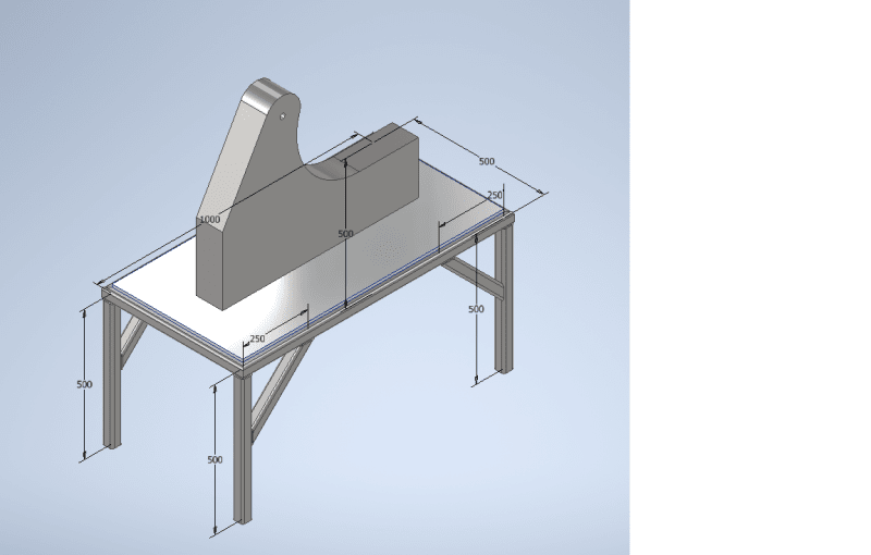
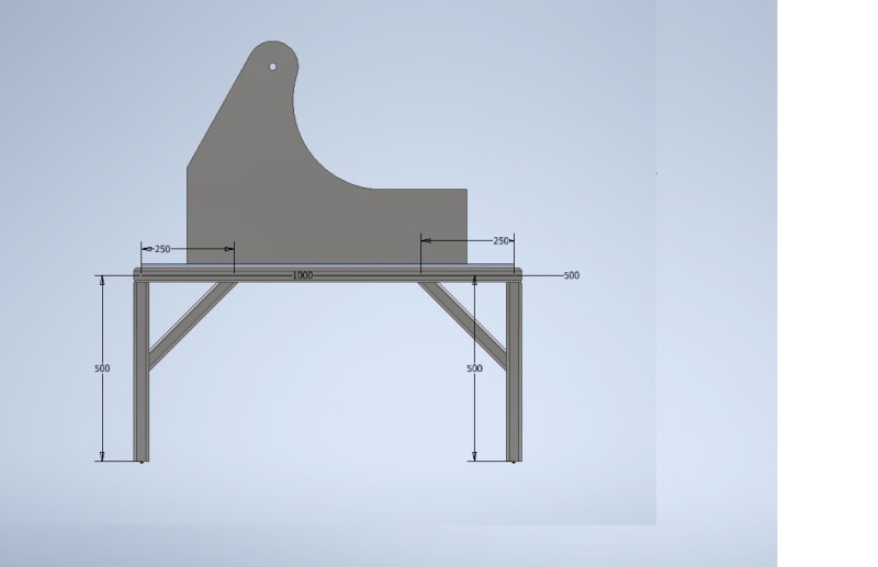
Image_1_hue48u.png

Image_2_nllsoz.jpg
 
Replies continue below

Recommended for you

In case of more complex, statically indeterminate frames you have to use advanced matrix methods common in structural engineering - force (flexibility) or displacement (stiffness) method.
 
For simple systems you can write a software in MATLAB/FORTRAN with the following steps.
1. Define node no, element no, geometry and section properties and input to software.
2. Calculate element stiffness matrix of each element.
3. Assemble global stiffness matrix by combining transformed element stiffness matrices.
4. Define load vector.
5. Define restraints and modify global stiffness matrix accordingly.
6. Solve for displacements Ax=F. A =modified stiffness matrix, x= displacements, F=load vector.
7. Calculate strains from displacements.
8. Calculate stresses from strains.

Engineers, think what we have done to the environment !
 
If the "machine" has rotating components or its function causes external or inertial forces the "frame's" design should go way beyond deflection and stresses.

Resonant frequencies can cause excessive vibration, process malfunctions and even frame cracking and breakage.

For the psst several decades my opinion of fan and pump manufacturers has remained that many consider the vertical loading on a frame or base, then make a drawing of a bunch undersized steel channels and plate welded or bolted up into rectangular frames, with little thought about load paths.
 
As the intention of OP is simplified analysis a static analysis approach was given. In simplified analysis dynamic loads can be analysed as static loads after multiplying by a dynamic load factor provided the natural frequencies are away from machine speed. But if eigensolutions are desired for the natural frequencies the same can be programmed with some additional effort.

Engineers, think what we have done to the environment !
 
it can be as complicated as you want, or as simple.

How to account for dynamic loads ? ... vertical loads and moments ... double for vibration effects ??

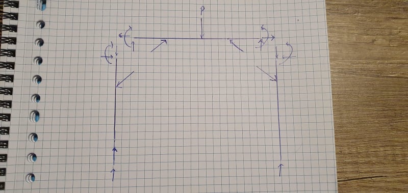
external reactions (make a free body of your table) ... vertical loads equally (or proportion by where the load is, if not central), moments are reacted as couples (equally between the two frames).

internal loads ... a little harder, but once you have the external reactions and the applied loads, not too hard (a frame with fixed corners, the load in the diagonal is the couple of the fixed joint).

for your structure, I'd make sure there's structure under the table top to distribute the load to the two frames (don't ask the table top to do this). Just two I-beams so that you "machine" attaches to them and they are clipped into the frames. You may need vibration isolators under the "machine".

another day in paradise, or is paradise one day closer ?
 
First of all, thanks for the comments. I'm primarily interested in static loading. Dynamic loading and frequencies is not of interest for me at the moment. I think it's importantly to first understand the static situation. So if you were asked to solve this structure statically (find major stresses etc.)how would you apporach this? How is this solvable for someone with basic knowledge of statics? Do I need to learn force (flexibility) or displacement (stiffness) method as stated before? Thanks in advance.
 
you may not be interested in dynamic loading, but it's a thing. Sure you can mean "I want to do a static analysis", then calc the dynamic loads and factor for quasi-static. Else risk getting it wrong and having to upsize later.

How would I approach a static solution ? Like I posted ! Figure out your applied loads, and the point of application. Having this point as close as possible to the center of the table. Then you can say vertical loads are equally reacted at the 4 legs, moments are reacted as couple evenly applied to each pair of legs. Then I'd consider the frames (equal, so one is enough). You know the external reactions, so then how do the applied loads load each frame. I suggested beams under the table-top to give a simple and straight forward loadpath from the load to the frames.

The "machine" is a free body, you know the applied loads, and you should be able to figure out the reactions, these are applied to the beam, and reacted at the frames.

Now the rest is "simple" beam analysis, method of sections.


another day in paradise, or is paradise one day closer ?
 
How is method of sections going to be helpful? Because all the connections are welded (not pinned) I'm having to many unknowns.

Image_FBD_irjzcs.jpg


I'm aware that dynamic loading is a thing but at the moment it is not within my ability's. I'm just trying to understand how static loading can be calculated in frames with too many unknowns and how people tackle these things.
 
a simple approximation is to consider the frame as a "simple" frame with fixed corners. This determines a fixed end moment. This moment can be represented as a couple between the corner and the diagonal which changes the simple frame results only inside the diagonals, so you need to re-calc things over this small span.
Screen_Shot_01-13-21_at_12.20_PM_seer6b.png


another day in paradise, or is paradise one day closer ?
 
To make it more complicated, consider the additional loads on the legs if the frame is pushed along the floor. Also, look at buckling of the legs.

For solving, I personally get a better feel for the problem of over constrained parts by looking at the relative stiffness paths.
 
one problem at a time ... the OP wants the simplest solution.

another day in paradise, or is paradise one day closer ?
 
I am not looking down on you, but a AA degree just does not provide you with the knowledge required for conducting frame analysis. I admire your willingness to learn, but it is a difficult subject to DIY by reading a few textbooks, or going through a few solved examples. Please consider to continue your education on campus, or online.
 
I totally agree with you "r13". I'm sort of a beginner in the engineering world. It's part of a carreer switch and a AD does not provide enough knowledge.

I have to conclude, by your comments, that at the moment it's probably out of my league and further study is necesarry. Can you guys recommend some other books/courses besides the book "dvd" recommended?
In my study we used statics by russell hibbeler.

Thanks everybody for the responses, I appreciate it.
 
Josv,

Here is a list of schools offer Civil Engineering courses online. You may follow up on schools that offer Mechanical Engineering online study. Link
 
it's a pity you don't have anyone there to mentor you. There are plenty of "strength of Materials" texts and online instruction, as R13 says.

But even if you know the theory, the devil is in applying it ... how to simplify the real world structure, such as your example, into pieces that fit within your theory.

The two things I'd offer ...
1) draw free body diagrams, of the whole structure and piecemeal,
2) look for loadpaths ... how does the load get from application to reaction.

GL

another day in paradise, or is paradise one day closer ?
 
Status
Not open for further replies.

Part and Inventory Search

Sponsor