I'm not an electrical engineer. Recently I learned that gas powered cogeneration plants (common on wastewater treatment sites) are poor replacement for a Diesel engine for an emergency power supply, and about another problem:
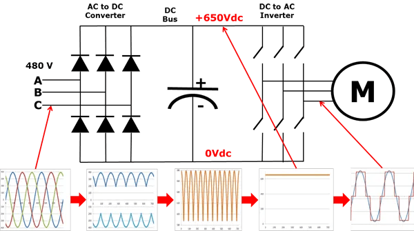
Frequency inverters produce high frequency signals on the side of the power input. This is relevant when designing an emergency power supply for a site with lots of VFD, apparantly it is advised to install far bigger alternators so the alternators don't get damaged by these high frequency voltaes (So for 100 kW worth of VFDs you would install a 200kVA generator on a 100kW engine). These high frequencies are explained by how an FI works:

The "switches" switch with the output frequency or far faster, to create the desired frequency and output voltage via pulse width modulation. This rectangular wave form of course creates high frequency signals.
Now here are my questions:
The DC Bus is mostly a capacitor, so it should essentially short circuit high frequency signals. Why, then, do we have high frequency signals on the input side?
Should it not be relatively easy to either separate the FI from the power supply with a band pass (50 or 60Hz) to block high frequencies, or protect the alternator in a similar fashion?
Frequency inverters produce high frequency signals on the side of the power input. This is relevant when designing an emergency power supply for a site with lots of VFD, apparantly it is advised to install far bigger alternators so the alternators don't get damaged by these high frequency voltaes (So for 100 kW worth of VFDs you would install a 200kVA generator on a 100kW engine). These high frequencies are explained by how an FI works:

The "switches" switch with the output frequency or far faster, to create the desired frequency and output voltage via pulse width modulation. This rectangular wave form of course creates high frequency signals.
Now here are my questions:
The DC Bus is mostly a capacitor, so it should essentially short circuit high frequency signals. Why, then, do we have high frequency signals on the input side?
Should it not be relatively easy to either separate the FI from the power supply with a band pass (50 or 60Hz) to block high frequencies, or protect the alternator in a similar fashion?
