Continue to Site

Eng-Tips is the largest engineering community on the Internet

Intelligent Work Forums for Engineering Professionals

  • Congratulations KootK on being selected by the Eng-Tips community for having the most helpful posts in the forums last week. Way to Go!

Friction Clamp/Brake Conundrum

Status
Not open for further replies.

NoelFa

Automotive
Jun 10, 2024
9
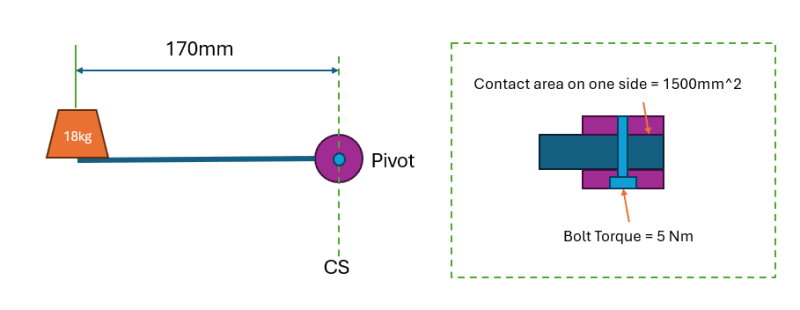
Hi guys, I am trying to design a brake/locking mechanism to hold up a weight, here is some background; I have a weight 18kg, 170mm away from the pivot point on an arm. A brake compresses the arm at the pivot point. This consist of a M10 bolt compressing a surface area of 1500mm^2 on each side of the arm. The torque I apply to the bolt/brake is 5 N/m. The CoF is 0.3. Will the brake hold up the weight? I am struggling to find the correct formula for this calc online. I know the weight will produce a torque around the pivot point of approx 30Nm. The clamping force I think would then be Torque/(CoF x bolt diameter) = 2.5 Nm. Is this correct?


On a different note, why does a taper help with these kind of friction brakes? I've seen it mentioned online but I'm not sure why. If the contact surface was at a 15° angle what would this do to the calculation?
 
Replies continue below

Recommended for you

Noel said:
The torque I apply to the bolt/brake is 5 N/m. The CoF is 0.3. Will the brake hold up the weight?

Almost certainly not.

Noel said:
The clamping force I think would then be Torque/(CoF x bolt diameter) = 2.5 Nm. Is this correct?

No, it's not.

Noel said:
why does a taper help with these kind of friction brakes?

 
Thanks for the feedback. What is the correct formula/approach to figure out the needed torque/clamping force to hold the weight? Hopefully the image below helps

Screenshot_2024-07-08_133404_ztacmj.png
 
Actually, it's a necessary formula to solve the problem.

OP has slipped ta step, and use it wrongly.
 
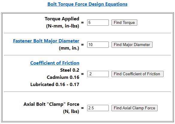
I had a very similar problem at work recently. I used the same calculator you did, except using .18 for the friction as that seems more indicative of zinc plated bolts from my reading.

axial force (from calculator) X frictional coefficient of your pad X effective radius of your clutch pad = net holding tq. You know what holding tq you need, just rearrange for the axial force. Then plug that back into the calculator for the clamping tq.

Area of the pad doesn't matter nearly as much as its location relative to your rotating axis. My clutch pad is round and concentric with my axis so I just used the centerline between the ID and OD of the pad as my radius (I know that's not how circles work but it was close).

I was going to math it out for you but I realized that I can't without knowing how your brake pad is positioned. But from what I gave you, it should be easy.

IDK if what I have is the most bullet proof method, but in my testing so far is has been experimentally confirmed.
 
Ok, great info, here's another stab at the math:

Arm/Lever torque around pivot point: 18 (kg) x 0.17 (mm) x 9.81 (m/s2) = 30 Nm

Bolt Clamp force: Bolt torque 5 (Nm) / Bolt diameter 0.01 (m) x CofF 0.2 = 2500 N

Average radius = 13 mm
Number of braking faces = 2

Torque from braking mech: Clamping Force x CofF x average radius x number of braking faces = 2500 x 0.2 x 0.013 x 2 = 13 Nm
Torque required: 30 Nm

Therefore I would need to increase bolt torque or play around with some of the other figures.

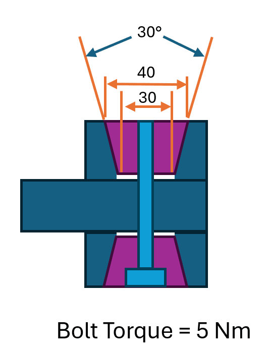
Assuming this calculation is correct, I read that braking force can be greatly increased by going to a conical shape, however I'm not sure how to do this calculation. Can anyone help with this? please see below additional data. If more info is needed please let me know. Thanks

Screenshot_2024-07-08_150431_jyomuq.png
 
Hi MintJulep, I really appreciate the nuggets of information but I'm not sure how exactly to apply this to my calculation. The only other relevant thing I found online was the following, but I'm still unsure how to use this too:

The taper is a wedge with angle α, that converts bolt axial force into a radial force, in proportion to; run/rise = 1 / tan( α ). If the taper angle is too small, the taper will self-lock, so not always release when you loosen the nut. That critical angle; α ≈ atan( CofF ) ; For CofF = 0.3, we get; atan( 0.3 ) ≈ 16.7° wedge angle. That is also the angle, above which, a wedge or a tapered pin will be ejected.


Your conical wedge increases the normal force on the friction surface, thus increases the friction force available for holding the load.

But, you still need to "ground" that, because your latest sketch is still dependent on the friction under the head of the bolt.

How does the torque created by the weight and the arm pass through each piece until it gets to "ground" - something that is able to hold the load.

This is the "load path", which is a fundamental part of understanding how machines work.
 
Status
Not open for further replies.

Part and Inventory Search

Sponsor