Hi everyone,
I would like to create a macro for Catia V5 (FTA) which creates ordinate dimensions for all holes. As a start, I would like to create a simple linear dimension between two holes that are not in line (vertically and horizontally). As depicted in the image (red), the linear dimension is, by default, aligned by the elements and is just the direct line between the two holes. I would need the line depicted in blue - which is the ordinate distance in the horizontal direction.

My current script for creating the red, straight linear dimension between two given cylindrical faces / holes:
Does anyone have an idea on how I can create the dimension to be aligned with the horizontal / vertial axis of the view (or by a given vector). Or if/how I can change this alignment after the dimension is created?

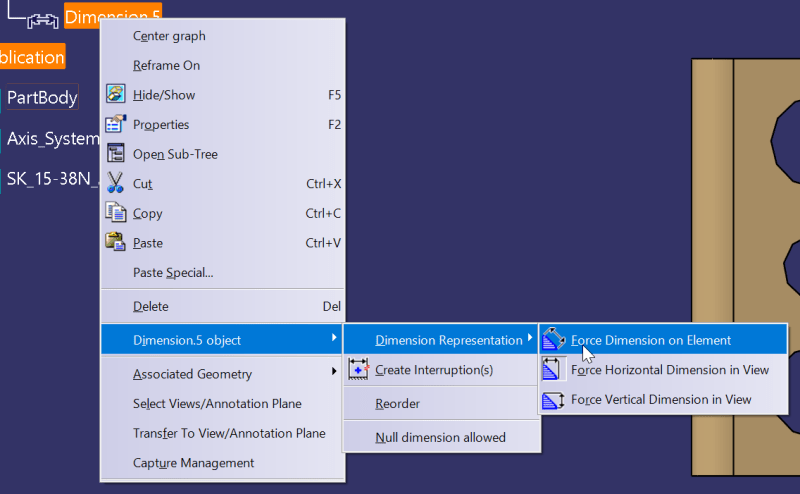
In the editor, this works nicely with a button in the dimension's menue. But I need to do this automatically, in a macro or via the c# api.
I would be very thankful for any comment/hint, as I'm struggling with this issue for several days now and did a lot of try-and-error experiments due to the quite incomplete documentation -.-
Thank you!
I would like to create a macro for Catia V5 (FTA) which creates ordinate dimensions for all holes. As a start, I would like to create a simple linear dimension between two holes that are not in line (vertically and horizontally). As depicted in the image (red), the linear dimension is, by default, aligned by the elements and is just the direct line between the two holes. I would need the line depicted in blue - which is the ordinate distance in the horizontal direction.

My current script for creating the red, straight linear dimension between two given cylindrical faces / holes:
Code:
Language="VBSCRIPT"
Sub CATMain(native_view,native_face1,native_face2)

Set partDocument1 = CATIA.ActiveDocument

Set part1 = partDocument1.Part

Set userSurfaces1 = part1.UserSurfaces

Set userSurface1 = userSurfaces1.Generate(native_face1)

Set userSurface2 = userSurfaces1.Generate(native_face2)

Set userSurfComboNode = userSurfaces1.MakeUserSurfaceNode(userSurface1, userSurface2)

Set annotationSet1 = part1.AnnotationSets.Item(1)

Set annotationFactory = annotationSet1.AnnotationFactory

Dim pmi as Annotation;
Set pmi = annotationFactory.CreateSemanticDimension(userSurfComboNode,5,0)  ' 5 = CATTPSOrientedLinearDimension; 0 = CATTPSDistanceDimension

native_view.Annotations.Add(pmi)

End Sub
Does anyone have an idea on how I can create the dimension to be aligned with the horizontal / vertial axis of the view (or by a given vector). Or if/how I can change this alignment after the dimension is created?

In the editor, this works nicely with a button in the dimension's menue. But I need to do this automatically, in a macro or via the c# api.
I would be very thankful for any comment/hint, as I'm struggling with this issue for several days now and did a lot of try-and-error experiments due to the quite incomplete documentation -.-
Thank you!
