Eng-Tips is the largest engineering community on the Internet

Intelligent Work Forums for Engineering Professionals

  • Congratulations waross on being selected by the Tek-Tips community for having the most helpful posts in the forums last week. Way to Go!

FTAO Shear Walls and the 4-Term Deflection Equation

Status
Not open for further replies.

phamENG

Structural
Feb 6, 2015
7,212
0
36
US
thread507-457014

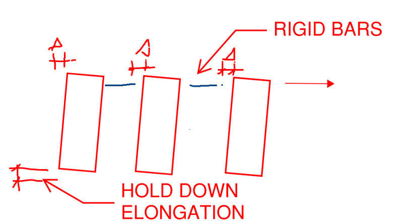
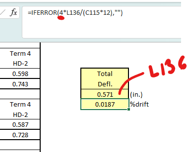
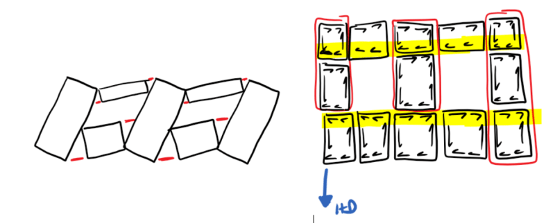
bones - I hope you're around today. Ever hear back about this from anyone? I've got a building with lots of windows all around that are driving pier widths way down. There's enough that using strong walls for their better stiffness isn't really an option - I'd just have strong walls and roof trusses. So I'm trying to drill down deeper into this deflection calculation and, though the data appears to track nicely with the hystersis and backbone plots, I can't rationalize the application of hold down deflections to piers without hold downs.
 
Replies continue below

Recommended for you

PhamENG -

That's a rough thing you're trying to do. I'm not sure there is a great method for doing this. Back when I worked for RISA, I was mulling over the idea of writing an article about how to use FEM plate modeling of the wall to get a better representation of the shear forces in the various panels of the wall (when compared to the various hand calc methds). I've kind of given up on that idea. I still think it's a good idea, I just don't think I'll ever find the time.

I should point out that I did a good amount of "validation" of the FEM method for wood shear walls back when RISA worked on it. I'm convinced that I could come up with an FEM model that would very closely model the 4 term (or three term) deflection equation of a single wall without openings. Then I could use the same modeling / meshing principles to model the various window openings, and come up with a better deflection representation for the overall wall than the "average pier" method.

Caveats, this would NOT cover cases where there were door openings between hold downs.... only window openings.

 
All that being said, for your case, I would ignore hold down deflections completely when doing individual piers. Take the average for each of those piers then do a "rigid body" rotation of the entire wall based on your calculated hold down forces to increase that deflection. Make sense?

Essentially, you start out assuming totally rigid hold downs. Calculate your pier deflections get an "average" deflection for your wall. Then super-impose an additional deflection based on rigid body rotation caused by hold down deflections.
 
Josh - that's where I keep ending up when I try to reason it out. Thanks for the validation. When I do that, the results are much more manageable.

I'm curious to see if bones ever got an answer, though, because including the hold down deflection at each pier seems to provide very accurate results according to the data published by APA.

 
I've spent a bit of time looking at this, as I recently created my own version of the APA spreadsheet, adapted to Canadian codes. I got the distinct impression that the focus of the APA when evaluating FTAO methods was on strap forces and that estimating deflections was an afterthought. The 2015 SEOC paper (https://www.apawood.org/Data/Sites/1/documents/technicalresearch/seaoc-2015-ftao.pdf) seems to give convincing plots showing how the APA deflection approach is accurate, so I've just mentally waved my hands and gone with it.

JoshPlumSE said:
Essentially, you start out assuming totally rigid hold downs. Calculate your pier deflections get an "average" deflection for your wall. Then super-impose an additional deflection based on rigid body rotation caused by hold down deflections.

This is a logical approach to me, except that I don't follow when the APA starts averaging deflections. To me, the shear distribution in the wall piers needs to be iterated to get deflections to match. Then again, much of the deflection calculations are empirically-based approximations, making much of this very hand-wavey.
 
This is a logical approach to me, except that I don't follow when the APA starts averaging deflections. To me, the shear distribution in the wall piers needs to be iterated to get deflections to match. Then again, much of the deflection calculations are empirically-based approximations, making much of this very hand-wavey.

That's a really good point. My guess is that this is mostly about trying to keep the method "simple".
 
Craig - I haven't checked it in detail, but I get the impression that the deflection is going to be pretty close between an iterative solution and an averaged solution. Once the aspect ratios of the piers get large enough to start making a measurable impact on stiffness, you get reduction factors that "increase" the demand. So the wall ends up a little stiffer than it "needs to be" for the tributary area approach. So you end up with these piers that all have "enough" cumulative strength and we've allocated some additional stiffness to areas that need it that are all connected by a common collector. Add to that some 'softening' of the wall at higher load levels, and it falls into line.

Maybe that softening is where this is coming from. Maybe it's not that there's hold down deformation at each pier, maybe it's that the panels aren't quite as rigidly fixed as we'd like to think. Fastener slip in the straps, at blocking, etc. would all degrade the stiffness and ability to transfer forces around openings. So maybe it's a happy accident that, in the testing, the hold down slip/elongation equaled the slip and slop in other parts of the wall. After all, all those tests were done using hold downs as corner straps. Coincidence?

 
Pham, yes I agree with you that the averaging of deflections and subsequent "errors" in shear distribution are likely small enough to ignore. The nitpicker in me would prefer not to wave my hands, that's all.

I had not previously noticed that the tests used hold-downs as analogues for the straps, but it makes perfect sense to facilitate the measurement of strap forces. I now am almost completely sold on the deflection calculations including hold-down deflection for piers without them - I can rationalize it as an analogue for the deflection caused by the straps at the window corners, which are not otherwise considered in the deflection equation (no fifth term for strap elongation).
 
Nope, I never got a response from APA. I posted my query in 2019 and I believe APA has done further testing and refinement of this method since then, so I might do some continuing education on this topic and see if I can come away with a better understanding. If they are "smearing" the deflection equations in order to backfit the test results, that would be a satisfactory explanation for me.
 
XR - insufficient strength.

Bones - thanks for following up. Maybe I'll try to reach out to them. The apparent accuracy is compelling, but I don't see the connection when taken literally.
 
I went back in to my FTAO spreadsheet from 2019 and compared to the worked example in the APA document T555 (revised January 2022). I still have a hard time matching their 4th term deflection calcs. I match their numbers for 3 out of the 6 pier calcs, but the other half do not match. Has anyone else been able to verify how APA derived those 4th terms in their example? It looks like their 0.459" for Pier 1-Left is off by a factor of 2, for example.

Also, I can't figure out how they came up with their value for % drift.

These are the numbers I get:

Screenshot_2022-11-14_081059_ldbxyc.png
 
I have been down this road an it gets very complicated. Non linear equations, wood shrinkage, multiple stories and base rotation, etc. It's complicated to the point where you are beyond spreadsheets and mathcad. It would be crazy to model these in FEA, so you just need to simplify and make some assumptions. There are no suitable off the shelf software packages for this.

If you pull out the holddown deflection, things get a lot simpler. Shear wall deflection on longer walls is roughly proportional to shear stiffness G and therefore shear strength. Bending deflection becomes a smaller factor for walls with a 2:1 ratio or better. Generally, the shear will distribute out based on wall length. That is an oversimplification, but there are some hearty safety factors on wood capacities. The stronger elements will take more load.

If you've ever dabbled in IRC prescriptive design, you know that their designs come up a lot leaner than an engineered design. And they still work.

For FTAO, I've used the APA approach from T555. It is something to hang your hat on.

 
bones - I was going to get some work done today....

manstrom - I agree that it's complicated, and a simplified solution is all I'm after. But the simplified solution still needs to make sense. My impression, so far, is that for the T555 approach they have taken the IBC 4 term equation and fudged a value to make it match the empirical data. I'm okay with that, I just want to know that (if, indeed, that is what they did.) I don't agree with taking it out. It may make it easier, but it also makes it less accurate and likely unconservative (apparently, based on the fit of the calculation and the empirical data as presented).

I've done a lot more than dabble in the IRC - and if you actually go through all of the detailing and rules, it's not much leaner. You save on a few hold downs, though if you have a well thought out and detailed uplift load path there's likely a hold down in most of those spots anyway. It also only works for a very small segment of the market - tract homes, essentially. The houses I do violate at least one, usually several, of the limitations of braced wall design.
 
phamENG said:
I can't rationalize the application of hold down deflections to piers without hold downs.

Don't we rationalize it like this? I've been imagining that all of the piers on a common line would experience the same, hold down related drift as the pier that actually has the hold down.

C01_vslic3.png
 
KootK, I always pictured that the piers without hold-downs (fixed at their base to surrounding wall sheathing) would be stiffer and therefore attract higher shear forces. Rather than a hold-down device, these piers are fixed by their chords being nailed to the shear wall panel that runs below the windows. Yes, that panel must deflect some, but it must be less sloppy than nails in a CFS hold-down.

I've had a nagging concern that the APA's FTAO calculations may not be conservative when estimating the maximum shear force in some piers because:
- They average the deflections and don't iterate the shear forces until the deflections match, meaning that some piers have underestimated/overestimated shear forces.
- The inclusion of hold-down deflections in piers that don't have hold-downs may function to underestimate the stiffness of some piers, leading to an underestimation of shear forces in these piers.
The potential for those two issues to combine and create a calculation error that is of consequence has nagged me at the back of my mind. At the same time, I have hesitated to break away from the FTAO calculation methods as that would seem a bit rogue, and the data to back up the method seems robust.

As Pham pointed out above, we don't account for strap elongation & slip in the deflection equation, so perhaps including the hold-down term is a quick and dirty way of accounting for this. I don't quite like that approach, but also do not have data available for strap elongation and associated nail slip, so I can understand the rationale for saying "hold-down deflection and strap deflection are both mostly related to nail slip in light gauge steel to wood connections and are somewhat comparable". And at the end, we waive our hands and say something about wood redistributing forces in remarkable ways...
 
Craig_H said:
As Pham pointed out above, we don't account for strap elongation & slip in the deflection equation, so perhaps including the hold-down term is a quick and dirty way of accounting for this.

Yeah, I saw that and, so far, feel that my explanation is more plausible.

Craig_H said:
Rather than a hold-down device, these piers are fixed by their chords being nailed to the shear wall panel that runs below the windows.

This illustrates my point. Once the tension chord delivers the load into the adjacent shear wall panel, where does it finally end up? I think that it ends up over at the real tension hold down. In this way, the "physical" hold down winds up being the "virtual" hold down for all of the piers. This bears some similarity to coupled shear walls in RC concrete.

Craig_H said:
And at the end, we waive our hands and say something about wood redistributing forces in remarkable ways...

In general, I agree, some of that is usually unavoidable. I don't feel that we need to make recourse to that here however.
 
bones - check out the screenshot below. I slapped together a quick and relatively open spreadsheet to show how I arrived at the same answers.

v.total is the total unfactored shear on the wall.
L.total is the total length of the shear wall (end pier to end pier only).
L1-3 are the tributary lengths of each pier.
v.1-3 are the shear values assigned to each pier based on tributary length.
v.total is just a verification to make sure it matches the original value (conditionally formatted to turn green when it's good)
h1-3 are the pier heights
b1-3 are the pier widths
T1-3 are the resulting tension forces at each pier that would be resisted by a hold down if a hold down were present
HD Cap and Def are the capacity and deflection at capacity values.
da.1-3 are the approximate deflections assuming a linear relationship between load and deflection at the hold down.
da(h/b)1-3 are the resulting deflections at each pier for the fourth term of the deflection equation.

Screenshot_2022-11-15_092329_bxwcca.png


bones206 said:
Also, I can't figure out how they came up with their value for % drift.

This one is a bit odd. They multiply the deflection by 4 and then divide it by the story height (96in). Haven't quite figured that one out yet.

Screenshot_2022-11-15_093159_p7mqaj.png
 
KootK - I agree with your approach for a portal frame, or perhaps for the cantilevered beam method of FTAO design (though I haven't messed with that much), but not the more popular/common Diekmann method. Your model ignores the fixity that comes from the panels below the openings.

See my sketch, below. As it rotates, we not only have a small, fixed beam element across the top, we have fixed panels at the base. That fixity and the shear/bending behavior of that run of wall panels below the openings will dominate. So the rotation at the base of each pier will be controlled more by the fixity of the panel below the window to the panel below the inter-window pier. So any slop in the strap will directly impact the rotation of the pier far more so than the hold down at the end of the wall.

It should also be noted that the hold down force used to determine the last term of the deflection equation is not based on the full height of the wall except for the last pier. It's only based on the sill to top plate dimension for the others. So the hold down deflections are not assumed to be equal at each pier.

Screenshot_2022-11-15_094211_di1m4b.png
 
phamENG said:
This one is a bit odd. They multiply the deflection by 4 and then divide it by the story height (96in). Haven't quite figured that one out yet.

Perhaps its the deflection amplification factor of LFWSW per ASCE 7-16 Equation 12.8-15.
 
Status
Not open for further replies.
Back
Top