ScottishRasta
Automotive
- Jun 15, 2020
- 1
I came across a thread from 2018 called "FULL R vs R" where it appears that no one actually knew the correct answer... so I wanted to clear up a couple of misconceptions.
I can only assume that everyone on the thread was too young to have worked professionally as a draftsman on the board.
(This is where I realize that I'm getting really old![[sad]](/data/assets/smilies/sad.gif "[sad] [sad]") )
)
BACKGROUND: Back before CAD was widely used as it is today, when the details where drawn manually (by hand), the FULL R annotation was intended for use on semi-circles (as one might see in a slot) in cases where calling out the diameter was not appropriate because the feature being dimensioned was not a full circle. The purpose of the notation was to assure suppliers that there wasn't a small indistinguishable flat between two radii instead of one continuous radius being shown (since everything was drawn by hand back then and you couldn't check the CAD file to see for yourself).
Although never stated on drawings, FULL R (as well as FULL RAD or FULL RADIUS) has always implied that both ends of the radius are tangent to the connecting lines/surfaces.
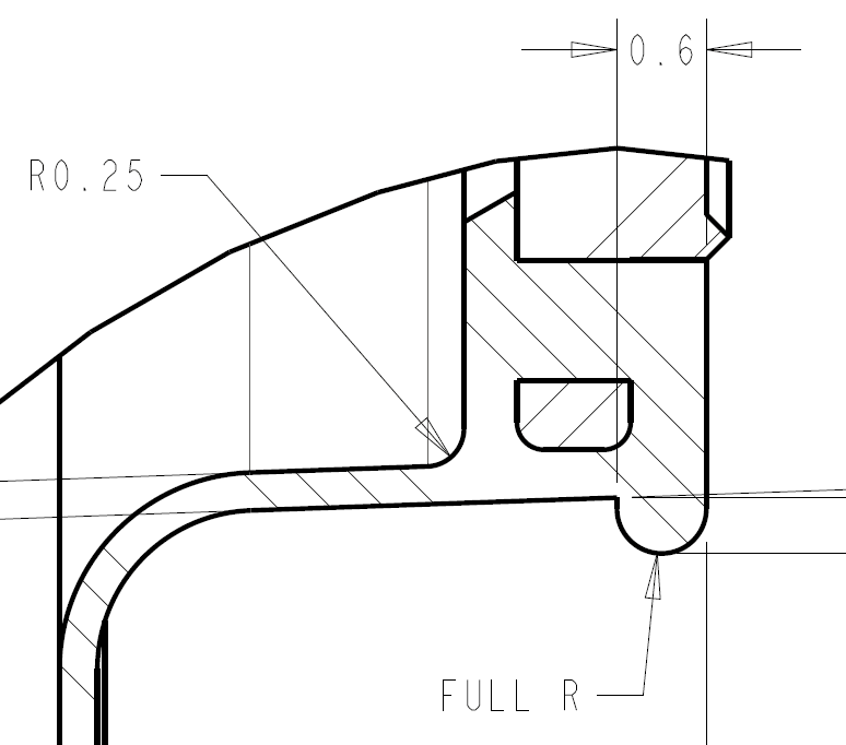
For product design, I believe that the more common usages for FULL R decades ago was in sheet metal forming to show that there were no minor flat sections in a 180° bend, for slots/mounting holes, or in seal/elastomeric applications like the one shown in the image below:
I hope this helps!")
I can only assume that everyone on the thread was too young to have worked professionally as a draftsman on the board.
(This is where I realize that I'm getting really old
)BACKGROUND: Back before CAD was widely used as it is today, when the details where drawn manually (by hand), the FULL R annotation was intended for use on semi-circles (as one might see in a slot) in cases where calling out the diameter was not appropriate because the feature being dimensioned was not a full circle. The purpose of the notation was to assure suppliers that there wasn't a small indistinguishable flat between two radii instead of one continuous radius being shown (since everything was drawn by hand back then and you couldn't check the CAD file to see for yourself).
Although never stated on drawings, FULL R (as well as FULL RAD or FULL RADIUS) has always implied that both ends of the radius are tangent to the connecting lines/surfaces.
For product design, I believe that the more common usages for FULL R decades ago was in sheet metal forming to show that there were no minor flat sections in a 180° bend, for slots/mounting holes, or in seal/elastomeric applications like the one shown in the image below:
I hope this helps!