Continue to Site

Eng-Tips is the largest engineering community on the Internet

Intelligent Work Forums for Engineering Professionals

  • Congratulations waross on being selected by the Eng-Tips community for having the most helpful posts in the forums last week. Way to Go!

Fuselage Skin Panel Shear Flow

admiral007

Aerospace
Mar 23, 2011
13
I’d like help solving for the shear flow in a skin panel.

I have a panel section in an aft fuselage. Section is unpressurized. It’s a skin panel framed by two stringers and two frames.

I have limited FEM data output (spreadsheet with output data on the elements). The FEM in the area I'm concerned is:
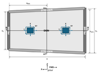
  • The FWD and AFT frames are built-up elements (CBARs and CQUAD) between and upper and lower node.
  • The upper stringer is two CBAR elements (FWD and AFT) with a node at the midpoint of the panel.
  • The lower stringer is two CBAR elements (FWD and AFT) with a node at the midpoint of the panel.
  • The skin panel is two CQUAD elements (FWD and AFT).
shear flow.png

Questions:
  1. In the examples I’m looking at (Bruhn, Niu, Flabel), shear flow is often just a stated value. I know that it’s shear load per distance, and VQ/I, but how do you calculate it from FEM data like I have?
  2. In these examples, the section cuts are always vertical (Sec A-A in my image). Is the shear flow in Sec B-B the same as A-A because the skin is assumed to be a pure shear panel?
  3. To get total load of the skin panel (FWD and AFT elements), do you just add the loads and moments together?
  4. How do you calculate the shear flow within the skin panel?
Flabel says that an approximation for the ultimate stress is 1.5 times the shear over the cross-section area:
eq1.png

Flabel also states that shear flow is the shear stress times the thickness of the skin:
eq2.png

So does that make the shear flow equation this?
eq3.png

Where V is the summation of Fxy of the FWD and AFT skin panel elements.

How off am I here?
 
Replies continue below

Recommended for you

there are some many ways to make one value from two.

1) simple numerical average,
2) weighted average
3) qav = (q1L1+q2L2)/(L1+L2)
4) yes, but the quads are not rectangles ... ok, replace the quad with an average rectangle (average opposite sides)

how different are q1 and q2 ?

how different are the areas, side lengths ?

I assume the same thickness in both panels ?

assuming panels are the same thickness, I'd probably average the fwd and aft edges, the top and bottom sides (to get a rectangle). I'd use a weighted (by side length) average shear flow (like 3 above) and call it a day.
There are many other approaches, more and less conservative, more and less analytical.
There is no "truth" (other than the structural test, and sometimes they lie[1] too).

[1] ok, the test doesn't lie, but our interpretation of the results can mislead (accidentally or intentionally).
 
The shear flow is just the shear stress (or shear running load) in the cquad skin elements; shear force/length = shear stress * thickness

VQ/Ib is for thru thickness shear, not in-plane shear.

And in your FEM, if you want the skin to only carry shear, you should be using cshear elements not cquads.
 
@rb1957 - thanks, That clears things up for me. I'm now getting values that seem reasonable that I can work with.

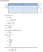
shear flow calc.png

@SWComposites - unfortunately, not my FEM so I can't change anything. I just have spreadsheet data 🤷‍♂️
 
well you still haven't made clear what "shear flow" you are refering to. is it:
- the inplane Nxy shear resultant "shear flow" from the Nxy or tauxy output of the cquads?
- or the thru-the-thickness shear from Qx and Qy output of the cquads?
and then what analysis are you going to use "q" for?
 
yeah, I have to say I have just about no idea of your calculation (or the relevance of calc).

I assumed you were looking at in-plane shear, but your calc is for shear flow over the thickness ??

What is "V" ? the out-of-plane shear ?? then membranes don't develop much out-of-plane shear ??

??

averaging in-plane shear isn't very scientific ... sure qav*(L1+L2) = q1L1+q2L2 has a certain balance (logic) to it;
averaging the in-plane areas of the two elements to make an "equivalent" rectangle only has the merit that our calculations typically assume rectangles (a/b).
I guess there are somewhere papers on trapezoidal shapes, but IMHO meh ...
 
OK, apologies. This is going be analysis for a cut out with doubler. I want to demonstrate that making the cut out and adding the doubler returns the panel to equivalent strength. Based on the low level of shear in the panel, the doubler will be sized to fit two rows of fasteners rather than be sized by any tension failure. I know fatigue and DT is affected and I'll look at that later.

I'm looking at Flabel Sec 9.3 - a doubler placed in a skin that is a pure tension field. In example 9-3, it's shown how to analyze this, but like I said initially, this example just states shear flow as a given value. I don't know what my q value is. I have FEM data output (but no FEM). I'm looking at the two elements that represent the skin panel that I want to cut out. The output I have for these two CQUAD elements is axial X, axial Y, shear XY, moment X, moment Y, moment XY, transverse shear X and transverse shear Y. I'm using in-plane shear XY as my shear value (V) and solving for q (VQ/I) in the skin at the vertical cut Sec A-A (by solving for q of the forward skin panel element and q of the aft skin element, then averaging them as the q for the skin panel as a whole). As expected, there are much higher axial loads in the stringers and frames, but my first look is at cutting out skin panel only so I'm only looking at skin panel element output. My understanding is that q, solved for at the NA of the skin, is constant throughout the entire area of the skin panel (which I'm guessing is why the offset cut out in the Flabel example 9-3 isn't accounted for in its analysis).

I made this post because I do not know what q is in my situation. My question is how do I solve for q in the skin panel? Is my line of reasoning as explained here flawed? If so, how?
 
ok, but where does the thickness come into it (other than shear flow = shear stress/t) ?

You have a very typical situation, where the FEM has two elements for the one piece of skin to be analyzed. Taking the average of the shear flows is a reasonable IMHO thing to do. Taking a weighted average (Qav*(L1+L2) = Q1*L1+Q2*L2) may be "better". The conservative approach is to use the larger q. Question ... did the FEM include a stiffener between the panels (did it model with CSHEARs ? then this stiffener should be the effective area along the edge of the panel, 30t^2 ... no, you say CQUADs, so probably not).

Then analyze the rivets for shear ... qL = F*n.

An option would be to consider the tension field created by shear (at 45 degrees, yes?) and show that these forces can be reacted by the rivets (in shear). You could use this to evaluate the whole patch with the average, an then look at the highest loaded corner as a detail.

But you should be getting help from where you are working, not from some random guys on the interwebs ... it is fine to admit you don't know something.

There may be something written up in AC43-13 (but I tend not to like this very old opinion).
 
q = shearXY in each element

since there are two skin elements, either conservatively use the higher q value, or use the average q value (maybe weighted by element size).

VQ/I has nothing to do with it.
 

Part and Inventory Search

Sponsor