admiral007
Aerospace
- Mar 23, 2011
- 18
I’d like help solving for the shear flow in a skin panel.
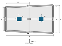
I have a panel section in an aft fuselage. Section is unpressurized. It’s a skin panel framed by two stringers and two frames.
I have limited FEM data output (spreadsheet with output data on the elements). The FEM in the area I'm concerned is:

Questions:

Flabel also states that shear flow is the shear stress times the thickness of the skin:

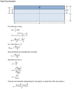
So does that make the shear flow equation this?

Where V is the summation of Fxy of the FWD and AFT skin panel elements.
How off am I here?
I have a panel section in an aft fuselage. Section is unpressurized. It’s a skin panel framed by two stringers and two frames.
I have limited FEM data output (spreadsheet with output data on the elements). The FEM in the area I'm concerned is:
- The FWD and AFT frames are built-up elements (CBARs and CQUAD) between and upper and lower node.
- The upper stringer is two CBAR elements (FWD and AFT) with a node at the midpoint of the panel.
- The lower stringer is two CBAR elements (FWD and AFT) with a node at the midpoint of the panel.
- The skin panel is two CQUAD elements (FWD and AFT).

Questions:
- In the examples I’m looking at (Bruhn, Niu, Flabel), shear flow is often just a stated value. I know that it’s shear load per distance, and VQ/I, but how do you calculate it from FEM data like I have?
- In these examples, the section cuts are always vertical (Sec A-A in my image). Is the shear flow in Sec B-B the same as A-A because the skin is assumed to be a pure shear panel?
- To get total load of the skin panel (FWD and AFT elements), do you just add the loads and moments together?
- How do you calculate the shear flow within the skin panel?

Flabel also states that shear flow is the shear stress times the thickness of the skin:
So does that make the shear flow equation this?

Where V is the summation of Fxy of the FWD and AFT skin panel elements.
How off am I here?

