Continue to Site

Eng-Tips is the largest engineering community on the Internet

Intelligent Work Forums for Engineering Professionals

  • Congratulations Toost on being selected by the Eng-Tips community for having the most helpful posts in the forums last week. Way to Go!

Gable End and Interior Shearwalls 4

Status
Not open for further replies.

medeek

Structural
Mar 16, 2013
1,104
I've been mucking around with the Woodworks software and reading through some of its documentation. I noticed that the uplift forces being calculated for the holdowns was different than I was calculating manually for gable end shearwalls. Looking through the help files I noticed that the height being used to calculate the holdown force was not the wall height but actually the average height to the roof diaphragm for that segment (see diagram below):

GABLE_SHEARWALLS.jpg


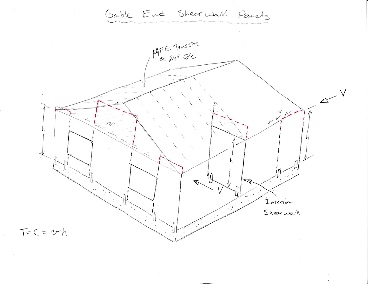
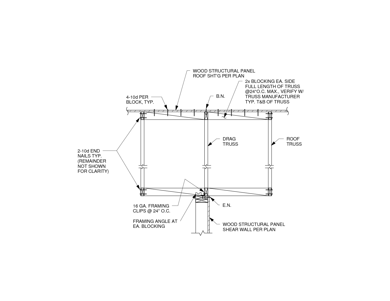
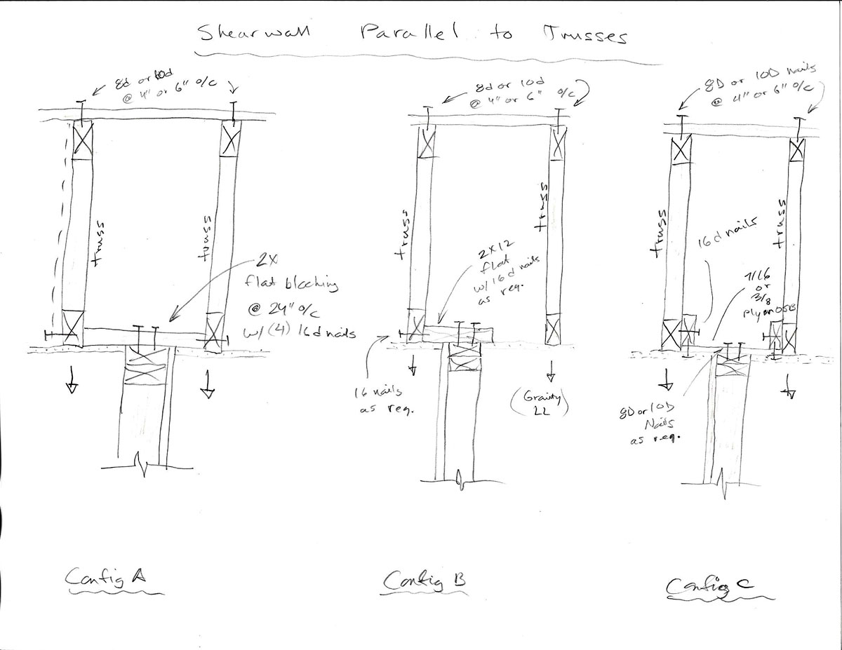
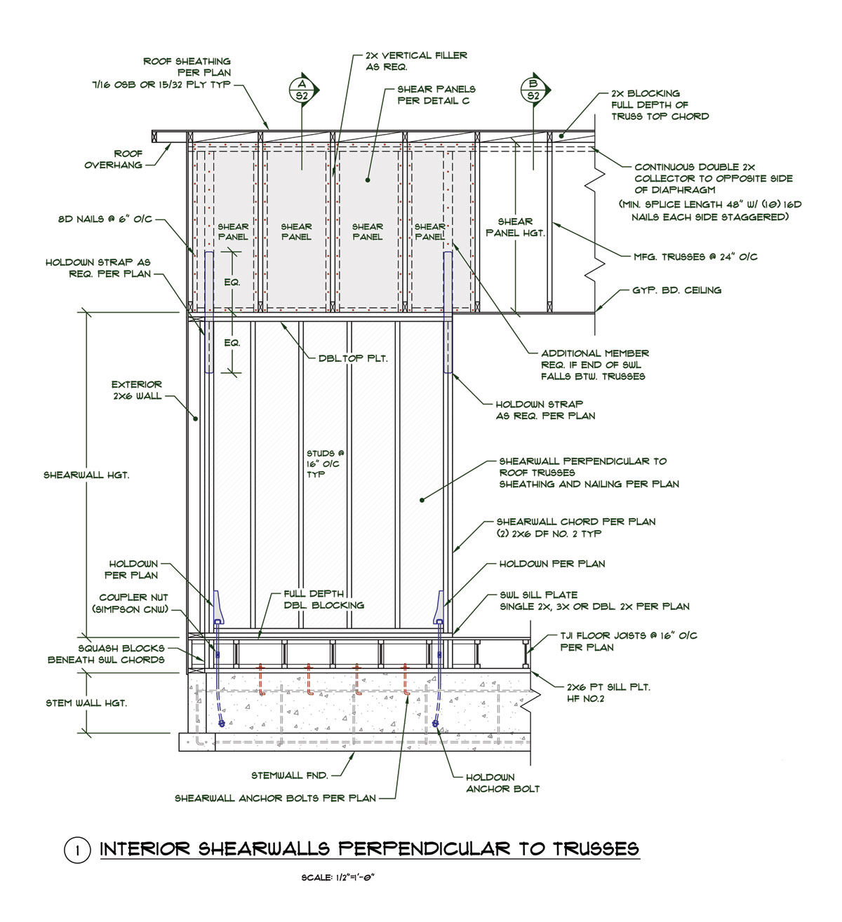
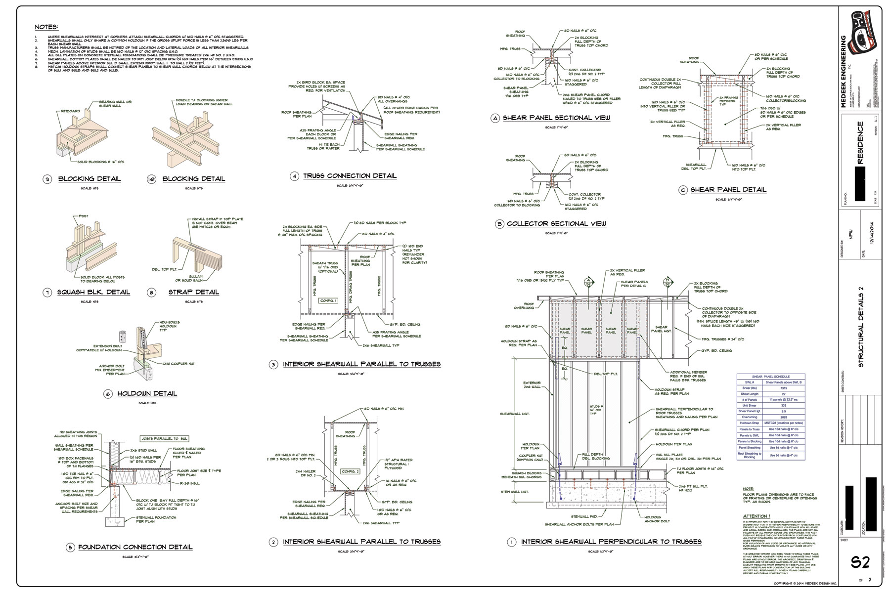
When a roof like the one shown above is composed of closely spaced trusses (max. 24" o/c) my thinking was they would act like mini shearwalls of their own and bring the diaphragm load down to the ceiling level where it would be transferred to the walls. I suppose the same argument can be made for interior shearwalls as shown above as well. However, I am now having to rethink this assumption.

The exterior shearwalls parallel to the ridge obviously are same height as the wall height but how is everyone else handling the gable end and interior shearwall heights?

A confused student is a good student.
 
Replies continue below

Recommended for you

I have used STAAD quite extensively in my other career as a mechanical/structural engineer so I am no stranger to using FEA to get answers. I think I need to give Risa 3D another hard look. If I could accurately model the framing members with the sheathing that would be huge for me since then I could at least see how well my manual calcs and assumptions are approximating the "real" solution. Of course one cannot afford to do this for every residential design (most of my jobs are usually not more than $300) as you suggest.

I have been digging through the WFCM as of late, and yes it does have alot of helpful prescriptive rules that I've also been incorporating in my own work. However, I've noticed that most of the residential designs that I'm looking at don't fit as nicely into the rectangular box model. I'm just trying to make sure that my engineering of these more elaborate structures is not woefully inadequate.

Brad805, do you or any of your colleagues have some sample Risa files of wall assemblies, diaphragms, portal frames or shearwalls that you would be willing to share. I would like to understand how such a FE model is created for a wood structure and what assumptions and details are made to make this an accurate mode.

A confused student is a good student.
 
As far as a business model based on residential work goes, think rich folks. I know a few structural engineers, including my spouse, that do quite nicely working on custom homes for the well to do. The trick is to develop a reputation for creativity and innovation. Things like:

1) Using steel beams to make wacky cantilevers work.
2) Features stairs in steel and glass.
3) Sexy heavy timber detailing.
4) Cross laminated timber floor slabs.

These kind of things get you out of the prescriptive domain and into operating in a space where your services are more highly valued (Brad's point). Your obvious attention to detail might serve you especially well in such an environment.


The greatest trick that bond stress ever pulled was convincing the world it didn't exist.
 
Chapter 9.8 of Terry Malone's book has a section on interior shearwalls perp. to trusses. After I finish digesting this chapter I will present my solution to the interior SWB above. In the meantime I found this interesting detail online which has relevance to SW2 and drag trusses that run parallel to interior shearwalls:

SWL_PARALLEL_TRUSS.png


Is this amount of blocking common practice for a typical drag truss? I suppose it will all depend on the loads involved.

A confused student is a good student.
 
The top blocking seems ineffective to me as the truss top chord is well braced.

I can see an argument for bottom chord blocking but, done like this, I have two concerns:

1) 24" o/c seems excessive.
2) The blocking is only as effective as the drywall diaphragm that restrains it.

I'd rather see diagonal bracing at some interval to laterally brace both the bottom chord and the joint between the truss and the wall.

An issue with this detail, and most of itss cousins, is the truss uplift that tends to occur with seasonal moisture change. It tends to put parts of these details into cross grain tension.

The greatest trick that bond stress ever pulled was convincing the world it didn't exist.
 
undefined said:
The assumption, in typical wood construction, is the the trusses/joists that have sheathing applied to the top and bottom is that it creates a system for the transfer of forces. As a system the lateral force at each truss/joist get transferred to the shear walls but the uplift force is resisted by each truss/joist connections to the bearing walls and does not get transferred to the shear walls.

I don't agree. For the overturning to be taken out at each truss, the lateral force must transferred to the bottom of each truss. The ceiling diaphragm (usually GWB) is not typically considered a diaphragm.

DaveAtkins
 
Dave,

I don't think I understand your point, but I"m probably missing something. Even if you didn't have a ceiling diaphragm, you could still take out the uplift at each truss / stud, right? It's like the roof is a folded plate and each stud on the uplift side is a string. They have no ability to resist horizontal forces but they can resist uplift due to rotation of the folded plate. The shearwalls then resist the tension from the lateral force applied at the top plate level.


EIT
 
The way I look at it, the lateral force is transferred to the resisting drag strut trusses and gable end trusses via the sloped diaphragms. It is then at these specific trusses that the overturning occurs.

Admittedly, this is an oversimplification. The entire roof (roof sheathing, trusses, and ceiling sheathing) may act as a unit. If so, many of the wall studs will assist with overturning.

DaveAtkins
 
DaveAtkins

The only way to match the design of conventional light-frame construction (per the IBC) with an engineered design is to look at the whole building. Such as, conventional light-frame construction requires an attic which has a ceiling creating a system that is not usually considered in an engineered design of wood structures. IMHO
The important thing is to design to your requirements/standards to meet the building code.

Garth Dreger PE - AZ Phoenix area
As EOR's we should take the responsibility to design our structures to support the components we allow in our design per that industry standards.
 
I have never done a FEM for a wood truss roof. The crux of the problem you are concerned with seems to be the impact of roof slope on the roof diaphragm and the flow of the forces. I believe the worst case will be a typical gable roof. Once you start adding hips into the mix the stiffness of the assembly will increase. You could make this roof as complex and accurate as you like, but I would start with something simple to calibrate the idea and keep the meshing simple. I would model a single truss as a 2D element assuming some chord dimensions and material strengths. From that it would be easy to create a 3D roof and then add a roof diaphragm element. Then I would likely add in some typical construction bracing and apply some interior restraints to get a better idea of the force distribution. To determine the shear wall load distribution you could assign spring constants, but I would likely start with pinned connections to check that the deflection appears reasonable. Spring constants will take some time to calibrate to get a reasonable load distribution. I suspect you would find the roof stiffness is greater than many of the simplifications suggest, and the roof will behave more like an assembly rather than individual components.

As we can clearly see from the respondents posting, the simplifying assumptions can vary. Most of the literature usually only covers the simple cases. From those we all develop rules of thumb we follow for our practice. There are some interesting practitioners in the residential engineering field.

The last detail you posted makes sense, but keep in mind the labor to implement that. A typical roof truss for a common house is approx $100 (can be less). The labor to cut all the blocking and nail them into place and can be more than adding an extra truss if the shear forces suggest you need more than one truss.

The interior shear panel you posted earlier can be a time consuming detail to implement. All of us engineers like plywood in these cases because it can be cut neatly cut to fit (in our minds anyway). From the contractors point of view on site he has to cut each 2x4, nail it into place and then attach the plywood. This is more time consuming than adding additional bracing between the trusses while they are installing the construction bracing. You can add a top/bottom chord member laminated to the vertical webs to create a truss of sorts. You will have eccentricities with that detail, but practical solutions will lead to more work long run. We do not typically get direct feedback on our designs, but you can be certain the framing contractor will make comments to the owners, or the GC about time consuming details.

For a $300 fee I hope you are working towards solutions that are in the realm of 2 - 5hr. You need a salary and must use a multiplier on that rate to account for the fact you are the IT, PR, HR, and accounting guy (assuming sole practitioner).
 
The best way to deal with shearwalls running parallel to trusses is to put the truss inline with the shearwall as shown above. I would have the sheathing continue all the way up the truss to the roof diaphragm sheathing. There will probably be a sheathing splice at the truss/wall junction so some A35 clips spaced accordingly would be advisable. The roof sheathing needs to be nailed so that the shear from the diaphragms on each side of the truss is accounted for, probably no less than 8d nails @ 4" o/c. Any closer spacing than this or larger nails will probably result in splitting of the truss top chord. In that case a 2x4 could be sistered onto the truss top chord for more nailing purposes.

The 2x4 blocking at the ceiling level seems pointless to me. The blocking at the roof diaphragm level would only seem appropriate if the shear was extreme, otherwise I would probably omit it or space it at 48" o/c.

After reading through Malone's book the thing that stood out to me was the necessity of making sure the deflection of the truss under gravity (live loads: ie. snow) loads does not compromise the lateral bracing.

A good case in point is the three configurations given below when the trusses do not line up with the shearwall. Both congfig A and config B will have problems from vertical loads and the blocking will probably be loaded beyond allowables both in bending and in shear or as in config B the blocking will be in cross grain bending or prying. Config C would be the best method to handle this situation, which allows for the vertical deflection of the trusses under gravity loads.

SHEARWALL_STUDY2.jpg


A confused student is a good student.
 
Based on chapter 9 from Malone's book the correct treatment of an interior shearwall that runs perpendicular to the trusses would be given as below:

SHEARWALL_STUDY3.jpg


What I find most interesting about this detail is the continuous 2x collector that runs the full length of the diaphragm with blocking. This seems like a lot more effort for the framers but without this collector the diaphragm boundary is not compliant with the IBC.

A confused student is a good student.
 
A couple comments:

1) I wouldn't sheath interior trusses unless you really don't trust the designer. It's costly and the truss itself should be easily capable if transferring the shear from the roof deck to the shear wall. Additionally, sheathing the trusses means interference with MEP runs.

2) I doubt the robustness of Malone configuration C to deal with upward and downward truss movement. Unless the shear wall is auspiciously centred between trusses, I suspect that there's still potential to snap that piece of plywood. I wonder if one could do something more flexible and ductile with sheet steel instead.

The greatest trick that bond stress ever pulled was convincing the world it didn't exist.
 
I agree the truss should easily be able to handle the lateral loads if the designer inputs them into his software. However, I don't like to trust any truss designers. I've worked with some that really know there stuff but then there are some that either don't care or are under such a time/money crunch they won't take the added effort to address the loads imposed by an interior shear wall. Sheathing the truss is essentially an insurance policy in my opinion.

I actually just finished helping my brother wire his house this summer. The structure is 52' x 36' with one interior shearwall parallel to the attic trusses. The sheathing extends from the interior stemwall all the way up to the ridge (12/12 attic trussed roof). I ended up boring about three 2" diameter holes through the shearwall sheathing up in the attic for the electrical work as well a number of smaller holes down lower. There was also holes for HVAC and plumbing interspersed throughout. None of this seemed too problematic, a cordless drill or sawzall makes quick work of 7/16 OSB.

With regards to truss deflection I suspect that the plywood could deflect a full inch before ultimate failure becomes a possibility. I wonder if OSB would behave better in this regard than plywood. Since you actually want the sheathing to bend easily in this situation I think it would be best to orient it along its weak axis. I might have to get into my garage and cut a 12" strip and support it at 24" o/c and load it in the center until it snaps, measuring the max. deflection just before failure. This would be an interesting imperial test of this configuration.

Assuming the sheathing bends in a arc like fashion a deflection of 1" vertically will result in a horizontal displacement of less than 1/16" for both bottom chords of the trusses, this should be acceptable.

The problem with Config A and B is the non-compliance of the framing and nails.

Sheet steel would probably work better than these two configurations however I wonder how well it would perform with the lateral loads. Would it tend to buckle or dish. Even worse would it make noise under high wind load that was cyclic in nature. If the shearwall was off center and quite close to one of the trusses I could see a much better argument for the sheet steel.

A confused student is a good student.
 
Buckling is definitely an issue with the sheet but it could be made to work. Maybe 1.5" corrugated metal deck would be the way to go. Pin fastened Metal decks don't seem to create noise problems in commercial buildings but, certainly, that would be a lousy outcome.

The greatest trick that bond stress ever pulled was convincing the world it didn't exist.
 
Interior Shearwall Detail cleaned up a bit:

INTERIOR_SWL_PERP_DETAIL.jpg


A confused student is a good student.
 
Here is the final detail page for the interior shearwalls if anyone is interested. I ended up having both types of interior shearwalls (parallel and perp.) on this project so it was a good study.

Interior Shearwalls

INTERIOR_SHEARWALLS.jpg


A confused student is a good student.
 
X2. Consider them pilfered.

I worry about the stability of the truss to wall connection in detail three. Does the ceiling drywall provide sufficient lateral restraint? Maybe one of our resident wood-o-philes can comment on standard practice.

I like to debate structural engineering theory -- a lot. If I challenge you on something, know that I'm doing so because I respect your opinion enough to either change it or adopt it.
 
See attached interior shear wall detail. Instead of sheathing the truss as shown, you could specify a drag truss as well. An alternative to the truss blocking is diagonal kickers similar to what you would do at a gable end.
 
 http://files.engineering.com/getfile.aspx?folder=aa3efd99-883b-4f37-970d-007f0861dec8&file=Interior_Shear_Wall_Example.pdf
In the previous detail that I found online I initially did not think the blocking at the ceiling level was of major importance, now I'm beginning to have second thoughts.

CBSE I like the mfg. truss block method in your attached file however if the roof is sloping that would complicate it slightly with different sizes of truss blocks, but the truss plant should have no problem in making them up correctly.

I also noticed you have toeinails as well as A35 clips into the top plate of the shearwall, normally I would do one or the other but I could see the redundancy in this connection.

I have never been a big fan of diagonal kickers but I suppose they are actually a better way to brace the bottom chord than even the horizontal blocking prescribed in this detail:

SWL_PARALLEL_TRUSS.png


A confused student is a good student.
 
Status
Not open for further replies.

Part and Inventory Search

Sponsor