Continue to Site

Eng-Tips is the largest engineering community on the Internet

Intelligent Work Forums for Engineering Professionals

  • Congratulations SSS148 on being selected by the Eng-Tips community for having the most helpful posts in the forums last week. Way to Go!

Gable end truss bracing 1

Status
Not open for further replies.

skeletron

Structural
Jan 30, 2019
881
I'm wondering what detail designers are specifying at the gable end truss. Recently, I have had two contractors immediately give me the gears for using a detail that was part of the company detail book. The key components are:
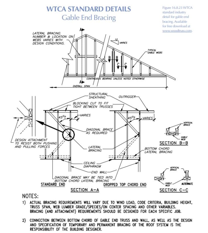
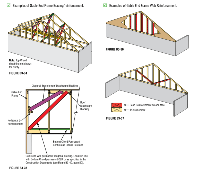
-drop top chord gable truss
-outriggers
-2x brace @ 2' up to the ridge blocking at the second truss

The question each contractor has is: why isn't the brace from the top chord to a "rat track" on top of blocking at the bottom chord?

Do you specify the brace going up or down? Why?

Any explanation I've been given offers:
-better resistance to uplift
-better stability
-historically always done that way
 
Replies continue below

Recommended for you

Bracing down to the bottom chord/wall interface. Since the framing is parallel with that wall and the ceiling can't be relied upon to act as a reasonable diaphragm, bracing down to the top of bottom chord/top of wall has the added bonus of bracing the wall against out of plane loads.

I've seen it done both ways, though. Occasionally in the same building (big X brace at each end of the roof).
 
There is an inherent knuckle-joint, by design, at the bottom of the gable end truss where it meets the wall plate below.

That joint needs to be stabilized laterally with a brace from the wall top plate to the second truss in from the gable end truss.

Mike McCann, PE, SE (WA, HI)


Skeletron:
The nature of the beast is that the joint at the gable wall top plates and the gable truss bot. chord is essentially a hinge in the gable wall framing. And, it should be supported in some way w.r.t. lateral loading and uplift. And, for that reason, I would brace from that wall top pl./bot. chord joint up into the truss system for 2 or 3 truss spacings. Often, that bracing is x-bracing for a several truss spaces (usually 4 or 6’) back into the roof truss system and roof sheathing, and is then combined with the rest of the general truss bracing system. Many of the truss manufacturers have very good, general pamphlets on truss roof system bracing, which is made part of their shop drawing, truss erection and arrangement drwgs. package, but the truss guys do not assume any responsibility for most of this, they’re just trying to be helpful and stay out of court. Builders most often pay little attention to these minor details, and you should check and inspect them. Poor roof truss bracing is often (maybe most often) the cause of these roofs failing during construction and even after completion. There are several levels of bracing involved, minimal construction bracing during erection and until the sheathing is on and the final general bracing is done, and then, some bracing of some individual truss members and chords. You should get your hands on a couple of those complete packages and study them for that industries’ general take on their roof systems. Maybe you get them during the shop drwg. review process, otherwise ask for a complete package for your own edification, maybe from several different truss suppliers, to see minor variations in their thinking.

The dropped top chord on the gable truss, and sometimes the first interior truss, makes the ladder framing for the rake and its soffit really clean and easy. There should be blocking (vert. 2x’s) over the gable truss top chord and btwn. each of the outriggers/ladders and there needs to be a little special detailing down at the rake and lower eave corner. This corner framing can be helped by using structural 2x sub-facia and rake boards, which also lead to a truer and straighter finished facia and rake. Some minimal hardware may be needed on outrigger back spans and for uplift at the gable truss and at the outriggers.
 
This issue is not specific to trussed roofs. it occurs in any conventionally framed gable roof and in 100% of the homes around here. In practice, the end wall is braced by the sheetrock ceiling and whatever perpendicular walls that occur. Have never seen a failure other than if a tree or automobile impacts the wall. I believe the IRC allows this but wants a balloon framed gable in high-wind areas.
 
XR250 - you're spot on there. As I recall you're up closer to the mountains. I'm down on the coast and everything is either balloon framed or has positive bracing at the joint. Makes "window walls" at the gable end with cathedral ceilings on the beach a real headache.
 
WTCA has an article (Link) on gable end bracing and suggests one detailing option.

I have a long standing dream that will never be realized wherein I'll design a horizontal, 4' deep, prefab truss to be installed at the ceiling level (no vaults).

c02_hkmsq5.jpg
 
BCSI has a truss bracing chapter in their guide to good practice for handling, installing, restraining & bracing of metal plate connected wood trusses.

A little bit of googling will get you there. but here's a snippet from the gable end bracing section.

image_vgxhzu.png
 
So is the truss manufacturer designing the truss for the additional up/down loads due to the braces? Are we tying the trusses down sufficiently to deal with the brace loads?
I have in the past done something similar to KootK's planar truss. I called out the last two trusses to be 1/2" shorter than the rest and sheathed the first 4 ft. of the ceiling with 1/2" plywood. The truss heels worked out in this job so it was possible. Got alot grunts from the GC, but it was installed. Probably would not do that again. I have also jambed a 24" LVL flatways in the first bay.
 
I feel like this topic, i.e. truss bracing, is one of those tried and tested type items. If you review the BCSI document, it rarely even talks about capacity of the bracing and more just gives maximum spacing of braces etc. Essentially provide a load path and pray.

Where I practice, I'm one of the few people that even shows the appropriate truss bracing on drawings. Most people just get lucky because the temporary bracing that the contractors install is typically left in place, and then that pretty much does enough of a job to prevent issues.
 
XR250 said:
So is the truss manufacturer designing the truss for the additional up/down loads due to the braces?

Smart ass. If such a truss engineering drawing exists, I want a copy to frame.
 
Wow. Thanks for the insight in this. As @jayrod12 alluded to, I *get it* in that the system is tried and tested and the intent makes sense to me but I *don't get it* because rattle my brain trying to put numbers to it.

Our detail looks similar to B3-35 above, but without the horizontal L-bracing. The issue came up in the field. The adjacent trusses are taller because the roof slope, thus the web members are conflicting where the bracing should be. I proposed modifying the angle or spacing, within reason, to suit.

I'll check out the BCSI document and the WTCA resources. I want to understand wood trusses a little more.
 
skeletron said:
The adjacent trusses are taller because the roof slope, thus the web members are conflicting where the bracing should be.

Another thing I have specified was a dbl. truss 4 ft. from the exterior wall and then ladder frame the rest. Keeps the space clear for braces without the pesky web interference.
 
Status
Not open for further replies.

Part and Inventory Search

Sponsor