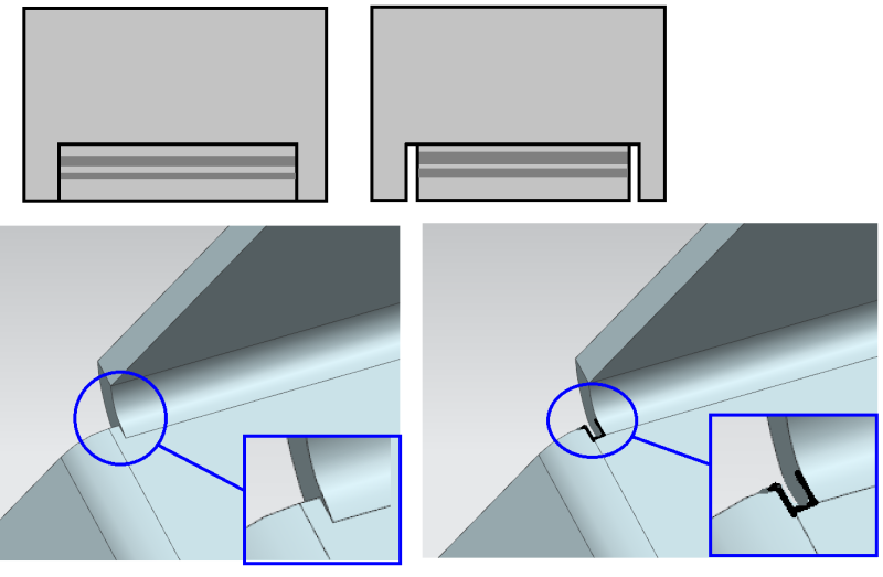
The subject of gap or no gap depends on the forming method and the final appearance of the part.
It is common for enclosures and cabinets to have a no gap corner when the final appearance is to be a close joint.
The main criteria for a close gap corner is the ability to form the part without tearing the corner.
Open gap corners are often used where the corner is welded to allow for penetration of the weld metal.
The exception to this is cabinets made of stainless steel that are often fused at the corners, where the gap is kept as close as possible, to reduce cleanup.
B.E.
You are judged not by what you know, but by what you can do.
What you are talking about is called "bend relief", googling that term will provide you with all sorts of reference material. Even though CAD software will allow you to show the bends working out without relief around them it won't work like that when you actually try to make the part.
The formed sheet metal bend with the relief cut at the end of the flange is one preferred approach. You could also make a helical surface transition from the flat section to the flange end face with the appropriate bend mold line allowance in the flat pattern. The image showing a formed transition with sharp corners is not practical.
The bend relief depends on the process of sheet metal flat creation, is the raw material stamped with dies, laser/water cut, etc. Talk to your manufacturer to determine what they use to save cost.
"Art without engineering is dreaming; Engineering without art is calculating."
Have you read faq731-376 to make the best use of these Forums?
If you have varying loads or vibration, it is good practice to round off inside corners to avoid fatigue cracks originating from the sharp inside corner.
In your first example (no gap), the cut should end in a round hole.
In your second, the inside corners of the slot should be rounded.
The third style is actually a very good suggestion/solution that removes stress from the bend.
The left picture is fiction, the others are both solutions. The shop that does your sheet metal may have a preference on how to do the corner reliefs, just like the other sheet metal parameters like k factor/bend allowance. You might talk with them before detailing and sending them your flat patterns.
A bearly tolerable reality is hard to model (i find that a lot these days ... the software limits are designing parts for us !) ... imagine you have a flat pattern and create both bends. you'll get some funky double curved result in the transition, probably a crack as well.
the 3rd with with the bend relief/undercut is typical in my business. that or putting a reasonably large hole at the intersection of the flange sides in the flat pattern, so that the two flanges never see one another (when bending the radii).
another day in paradise, or is paradise one day closer ?
KalleBoy:
There is a good article (“DFM and Sheet Metal”, that is, Design for Manufacturing and...) on this general subject in the latest issue (NOV16) of Machine Design mag. Go to machinedesign.com, if you don’t get the mag. To do a good design, you do have to know a great deal about how it is going to be manufactured, as mentioned above. A good design is also flexible enough in its detail to allow for some minor variations in detail as a function of the tooling the shop uses, and for best results you and the shop should be cooperative in meeting what they can do for the best final product/part results.