Eng-Tips is the largest engineering community on the Internet

Intelligent Work Forums for Engineering Professionals

Gasket failure heat exchanger 1

Status
Not open for further replies.

leon_har_dt

Mechanical
Nov 3, 2022
27
0
0
CL
Hi!, i'm a new member.
First, i want to make a recognition and gratitude to this forum and the people who participate in. I always can find some guide to solve my problems and that it's thanks to the community.
I'm facing a problem wich I could not found a guide by searching it here (beside that english it's not my first language i did my best effort)
In my first year of engineer(mechanical) i had to design two heat exchangers who work with water(shell) and oil(tubes)(water heats the oil).
The design temperature and pressure it's 266F(130C) and 145psi(10bar)(for both circuits). I selected a PFTE gasket chesterton ecs-b e=1/16" for a B16.5 Slip on flange SA182 F304L.(the tubesheet was made of a blind flange, same characteristics). The HX was tested in the shop at 13bar(188psi) and didn't present leak
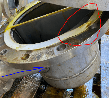
The problem begins when the customer was running their test and one of the HX leaked in the flange joint, we change the gasket days latter. The other one didn't present any leak and was use in the plant operation. Then the second one present leak, and analyzing the gasket(picture down below) it fail in a very similar way than the other
The customer said that the circuit consist of a recirculation circuit 1 bar pressure, and an impulsive circuit 7bar pressure (maintaining some vessel level of fluid)
flange_hwoelh.png

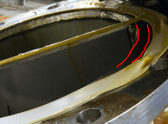
Here you can see the deformation of the gasket when the second HX leaked days latter when then plant return to operation(this gasket was not the one who was replace). Red lines pictures the original form of the gasket.
After writing the context. ¿Could this effect be caused by water hammer or surge when the system change from 1bar to 7 bar or vice versa?
or ¿could be when the plant return the operation and the sudden change in pressure deform the gasket?
What else could be the reason?

I'm analyzing the change of gasket material and even the type of gasket being compatible with oil and B16.5

I would be grateful if you could expand my mind in this problem

L.
 
Replies continue below

Recommended for you

PTFE’s nature as an inelastic material means that reuse or multiple installations of the same seal will not be possible.
 
I could be explained myself in a bad way, but when we changed the gasket we put a new one in the HX. The gasket in the photo had 1 week of operation, so i dont really understand your point :C sorry for that.
When i said that the plant return to operation, i mean it like on/off operation.
 
I'm not throwing away the possibility of creep, but in the next image, you can see that the affected zone is on the opposite site respect to the oil inlet blue arrow(btw it is vegetable oil). That's why i asked about water hammer/surge effect. You can see in the red zone that the gasket was deform just in the bolt area


flange2_fr7hlv.png


I would look into the creep behavior and look after another material just in case.
 
Your gasket creeped and lost its friction with the flange faces. Without this frictional restraint it is not capable of resisting much pressure without slipping and extruding. Any thermocycling will result in this type of failure.
 
leon_har_dt, I agree, creep It might have worked in a confined joint. Yours appears not to be so. Can your try a soft faced-mettalic gasket such as a graphonic style (Corrugated Metal Graphite Covered - CMGC)? Talk to your gasket vendor.

Regards,

Mike

The problem with sloppy work is that the supply FAR EXCEEDS the demand
 
I don´t know how your process works but water shouldn´t be allowed to goes in tubes side becouse of cold water expansion. On shell side, hot water, during start up is it possible to have a water hammer. The damage of your gasket is in tubes side isn`ít?

regards

luis
 
The other set of questions go like this;
You measured the flatness of the flanges, correct? (in all directions)
You are using the correct bolts and large, hard washers to spread the load?
You torqued this in a cross pattern in three or four gradually increasing steps, and then retorqued at the final values twice?
With a gasket that so little ability to spring back you need super good flange condition and the bolt up needs to be perfect.

= = = = = = = = = = = = = = = = = = = =
P.E. Metallurgy, consulting work welcomed
 
Seconding what Ed mentioned.

Bolting procedures, refer to ASME PCC-1 for guidance on flange assembly.

Gasket selection, I would try CMGC (Grafoil) or GMGC (Kammprofile)
 
Thanks a lot for your response, I will try to respond to all of you. (I'm going to ask with the context of learning, not to disprove your knowledge)
-compositepro: make sense to me what you say about frictional restraint, but, can lose to much even when it has been done an hydrotest?(i mean, i know a little how it works the creep phenomenon, but lose that much in 1-2 week of operation?)

-SnTMan: i will investigate the gasket that you sugest :)

-0707: it's not my process, oil goes through the tubes. I'm actually the HX manufacturer. I mentioned water hammer but in the oil circuit, like a ¿oil hammer perhaps? (sorry if it's sound a little silly jaaja)

-EdStainless and RJW000: yes, we acquire the PCC-1 and we are currently incorporating this procedure in our company.


Btw, i'm not ignoring the creep effect that you are all saying, I'm just want to go to the bottom of it and learn everything of this case :)(even more that i'm starting my mechanical career)
One learning for example it's that in my future design, i have to anticipate how the client plant works or make sure that an external factor it is considered. But in the other side, it's fair to say that are another responsibilities playing on.

Funny story, when I was looking in engtips about this case, I ended up with a phrase something like "the gasket it is let to the ultimate step of the design and/or it had to "support" or take into account other failures in other places of the equipment or the installation"
Best regards.
L.
 
PD: i ended up with PTFE gasket, and the ECS-B chesterton type, because of the alimentary requirement of the equipment.
I'm going to investigate the gasket options with this type of requirements as well.
 
leon_har_dt
1) Can you tell us the diameter, length and material of the stud? Also gasket width.
2) Check the calculations, the width of the gasket seems excessive.
3) Did you use torque or elongation? Lubrication?

Regards
 
Years ago I was able to take a course on the subject of making up gasket joints.
There was an instrumented flange assembly that we practiced on.
It was amazing how much the clamping pressure on the gasket changed as you tightened the joint.

= = = = = = = = = = = = = = = = = = = =
P.E. Metallurgy, consulting work welcomed
 
leon_har_dt, I might have added that these gaskets can be faced with materials other than graphite..

The problem with sloppy work is that the supply FAR EXCEEDS the demand
 
Hi!
r6155: 1) it was a 7/8" x 4" UNC bolt. Material it was a zinc plated grade 5(because it is what is available here in the market, we are trying to get SA193 B7 or B8)
2) The width it is the measure of the raise face and the ID of the flange. width it is 1/16"
3) Only lubrication. We measure the torque by a torque wrench. I'm recently learning about elongation with PCC-1

EdStainless: woow, I'm thinking of acquire the ASME guide course of "the bolted joint". Sadly, it's going to be online course :c

SnTMan: here i don't fully understand your point :C, you mean that the gasket that you suggest can be face over a SS304L material flange? or another gasket?

Thanks again :)

L.
 
leon_har_dt, what I meant is that the metallic core need not be faced with graphite. It could be faced with PTFE if you are tied to it for some reason. The corrugated metal core is most often SS but can be other metals as well.

The problem with sloppy work is that the supply FAR EXCEEDS the demand
 
Status
Not open for further replies.
Back
Top