Eng-Tips is the largest engineering community on the Internet

Intelligent Work Forums for Engineering Professionals

GD€&T in SolidEdge Draft

Status
Not open for further replies.

Pekkeri

Mechanical
Nov 6, 2018
11
0
0
EE
Hi,

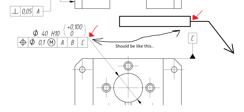
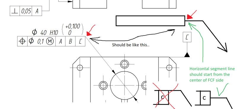
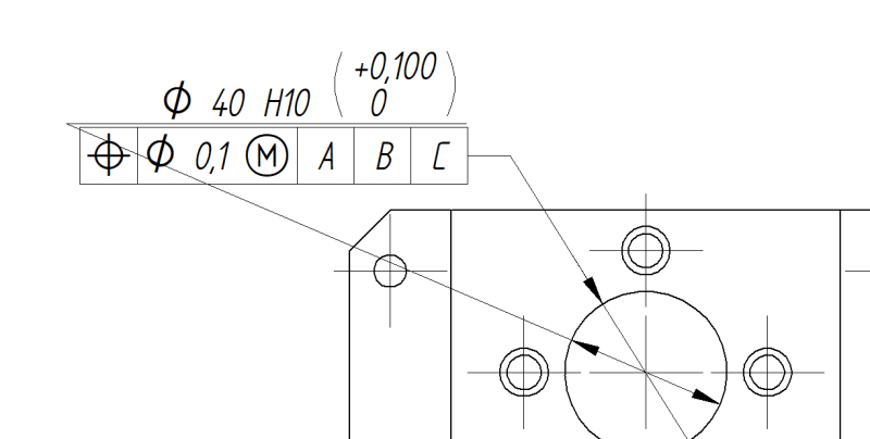
I`m currently using SOlidEdge ST9 and creating a part drawing in draft. I want to apply a position tolerance to a hole and also show the hole diameter (with tolerance class) above the FCF as stated in ISO 1101. How to put the hole dimension above the FCF? The situation can be seen on the picture but this is obviously no solution..

HOLE_FCF_rxcufe.png


BR,
Pekkeri
 
Replies continue below

Recommended for you

Select the FCF.
In the Command Bar, turn off the leader line.
Grab the FCF and drag it on top of the dimension.
It will attach to the dimension.
You can then snap the FCF to different locations, including the bottom of the dimension.

--Scott
www.aerornd.com
 
Thanks for the answer swertel.

I did as you suggested and got some results but it`s still not 100 % the way I want it to be (please see the pic). Maybe I misunderstood the snapping to dimension part.. when I drag it on top the dimension then the dimension highligths (in red color) but nothing else happens.. I can still drag the FCF anywhere and the dimension stays in place.
HOLE_FCF2_yiqejj.png
 
Also on the Command Bar.

With the dimension selected, there is an icon to select a horizontal segment to the callout.
Command_Bar_fvdv2d.png


In the image above, it's in the set of icons at the right side of the bar, just to the right of the leader line icon (which is orange).

--Scott
www.aerornd.com
 
So you use callout for hole dimensioning and not smart dimension? In this case how to you apply tolerance class with deviations to the hole nominal diameter(as in my example)? If I use callout then yes the FCF snaps to the dimension line but it snaps to the upper corner or lower corner of the FCF. But according to the standard the horizontalt segment of the line should start from the center of either of the FCF vertical side (pic). Maybe there is actually no way to get it right in solid edge..
HOLE_FCF2_l7hmru.png
 
I have an academic copy of ST9 so i´m not sure if you can open it. But i made another explanatory pic. I can create the FCF the way you did in your pic and i can but the hole nominal diameter on top of the FCF (with Callout). Additionally i can put the tolerance class behind the nominal dimeter by manually typing the tc to the callout(e.g. H10). But i cannot add the deviations shown in parenthesis (pic).

Hopefully I made my problem somewhat clearer.
HOLE_FCF3_jeonjy.png
 
Status
Not open for further replies.
Back
Top