I've been on this site a couple times before and have decided to make a profile, so this is my first post. I'm also a fairly new engineer, so please excuse my ignorance. I tried searching the forums for this topic and didn't find anything, so hopefully I'm not duplicating any threads.
The process and the outcome for the physical part that I mention below are well established and won't be changing, I'm just trying to figure out the best way to document it.
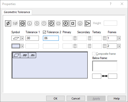
I'm working on a drawing for a plastic (match metal mold) part. During cooling, the walls can deflect quite a bit. One wall in particular is allowed to deflect inward by a certain amount, but it is not allowed to deflect outward. I was originally thinking of using a straightness callout, but now I'm thinking that a flatness callout for that wall would be the best way to go. In Solidworks, the Geometric Tolerance Properties window has a tolerance field with an optional second tolerance. Normally, a geometric tolerance is a ± condition, but I was thinking I could use the dual tolerances for a (+) / (-) condition. Please see the attached image.

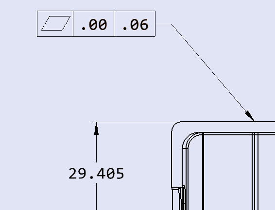
If this is even allowable, I wasn't sure which should be the (+) condition and which should be the (-) condition. As I'm writing this, I'm thinking that the (+) and (-) directions would be relative to the dimension for that wall, so maybe the second image would be correct.

The questions:
[ul]
[li]Is this an allowable way to control the amount of deflection in that wall?[/li]
[li]If so, which tolerance field should be the (+) condition and which should be the (-) condition?[/li]
[li]If not, what would be a better way to control the amount of deflection?[/li]
[/ul]
Thank you,
Bryson
The process and the outcome for the physical part that I mention below are well established and won't be changing, I'm just trying to figure out the best way to document it.
I'm working on a drawing for a plastic (match metal mold) part. During cooling, the walls can deflect quite a bit. One wall in particular is allowed to deflect inward by a certain amount, but it is not allowed to deflect outward. I was originally thinking of using a straightness callout, but now I'm thinking that a flatness callout for that wall would be the best way to go. In Solidworks, the Geometric Tolerance Properties window has a tolerance field with an optional second tolerance. Normally, a geometric tolerance is a ± condition, but I was thinking I could use the dual tolerances for a (+) / (-) condition. Please see the attached image.

If this is even allowable, I wasn't sure which should be the (+) condition and which should be the (-) condition. As I'm writing this, I'm thinking that the (+) and (-) directions would be relative to the dimension for that wall, so maybe the second image would be correct.

The questions:
[ul]
[li]Is this an allowable way to control the amount of deflection in that wall?[/li]
[li]If so, which tolerance field should be the (+) condition and which should be the (-) condition?[/li]
[li]If not, what would be a better way to control the amount of deflection?[/li]
[/ul]
Thank you,
Bryson
