Continue to Site

Eng-Tips is the largest engineering community on the Internet

Intelligent Work Forums for Engineering Professionals

  • Congratulations KootK on being selected by the Eng-Tips community for having the most helpful posts in the forums last week. Way to Go!

GD&T for centreline positioning? 1

Status
Not open for further replies.

hobbs101

Mechanical
Aug 1, 2012
74
Hi. I have a plain square plate of unknown exact size and I want to ensure that 4 holes on a 100x100 square pattern are positioned centrally and oriented correctly. How is this dimensioned/toleranced?

I've seen many drawings where plate centrelines will be marked and =100= dimensions are put between holes. Obviously this is dimensioning from virtual centrelines and is difficult to inspect.

How is it done 'properly' using GD&T?

Hobbs101
Mechanical Design Engineer
 
Replies continue below

Recommended for you

Make the height and width datums and position the holes relative to those datums (which are the theoretical centerlines of the height and width of the plate).

"Know the rules well, so you can break them effectively."
-Dalai Lama XIV
 
hobbs101,

Your drawing is interpretable by ASME Y14.5, but it is not necessarily what you want. A sloppy outline is not a good FOS datum feature. If your outline is sloppy, I would use a hole as a secondary datum, and another hoe or one edge as a tertiary datum.

What are you trying to do? Are you trying to locate your holes accurately enough to accept screws, in an otherwise sloppy part? In addition to allowing screws, are you trying to centre the holes within the otherwise sloppy outline?

--
JHG
 
As far as I understand, my drawing positions the hole pattern (not specifically the holes, but the complete hole pattern) on the centre lines of the plate.

On second thoughts, I'm not sure my drawing is correct. What's saying that the hole pattern centre should be on the centrelines?

What I'm trying to do is to position the holes centrally on a cast plate. The plate has a sloppy outline. But, I don't care about the outline, all I want to define is that the 4 holes are positioned centrally relative to the centre lines (i.e. the median planes of opposing sides).

Hobbs101
Mechanical Design Engineer
 
hobbs101,

Centrelines on your drawing indicate that your design intent is symmetry. How important to you is symmetry? Is it just your nominal condition, or do you have an additional need to control for it.

I would avoid FOS datum features on a casting. If you model your part symmetrically and use an edge and one end as your datums, and you dimension from these, you still get a nominally symmetrical part. You get unambiguous fixturing as well.

--
JHG
 
See attached for a similar example given in the Y14.5 standard. (You may not require the "M" modifier after datums B and C, but that depends on the function.)
Your dimensions of 100 would be basic (boxed) dimensions, and are assumed to be centered on datums B and C, which are the center planes of the part.


John-Paul Belanger
Certified Sr. GD&T Professional
Geometric Learning Systems
 
 http://files.engineering.com/getfile.aspx?folder=a3de698f-cd26-4d90-8e17-75860117c81a&file=FourHoles.pdf
I guess it does depend upon whether you need to tie down ...
a) the relationship between the holes
b) the positioning of the hole pattern to the plate
Of course it's likely to be both but it's always worth considering whether you really need both (naturally GD&T is there to allow you only to tie down just what you need.)

JP Belanger's example from Y14.5 looks close.
The one thing I would question is the assumption that the 24 TED's are centrally disposed.
The cross-hair in the center only extends to just beyond the large circle so I would argue it only applies to the circle.

Personally I would add two TED's from the datums and keep the datums as the real faces.
HolePlate_i99ykx.png


Just my take on it!!
 
Hobbs and John,
Although your examples don't show it, wouldn't you want the primary datum to be the front or back face?
Also, it greatly depends on whether you want to locate the holes around the center of the part, or from the edges as shown by John. If you want them located around the center of the part, then the two datum triangle symbols would be in line with the width and height dimensions. ( And if the latter, then the location of the holes is presumed to be centered, per the Y14.5 rules.)

John-Paul Belanger
Certified Sr. GD&T Professional
Geometric Learning Systems
 
Belanger,

JonSelby's sketch shows what I was suggesting. A cast FOS is not a good datum feature. As shown, the part is nominally symmetric. Assuming you apply a sloppy profile tolerance around the outline, the variations of shape will be asymmetric, but does this matter? You also have the option of a composite FCF, showing the relation of the hole to each other, separate from their relation to the datums.

--
JHG
 
Do I understand the distaste for using a cast FOS as a datum is rooted in the inability to make efficient hard-gages?

If so, it's not really an issue here in the small-quantity world, where CMMs are the most common inspection tool for complex parts. If designing for a case where that is the most likely inspection outcome, it would certainly be a nonissue to specify Datums A & B as being the centerlines of either width/length features.

Obviously only applicable depending on the context of the OP's situation.
 
Drawoh --- I gotcha. I was merely looking at Hobbs' original request, where the holes were to be "positioned centrally" on the part. Shrug.

John-Paul Belanger
Certified Sr. GD&T Professional
Geometric Learning Systems
 
AndrewTT

TED means Theoretically Exact Dimension - or BASIC dimension - or BOXED dimesion
 
AndrewTT

Keeping it official .. a definition from Y14.5 -2009

1.3.23 Dimension, Basic
dimension, basic: a theoretically exact dimension.
 
Jon Selby, the OP is asking for the holes "positioned centrally and oriented correctly" your scheme does not achieve that.

On the example Belanger links datum's B & C are not the faces, they are the center planes. Referencing those datum's in the FCF for the holes is what allows you to 'assume' symmetrically places around those datum's because the tolerance in the FCF says how far from symmetrical they can be.

I has nothing directly to do with what center lines may or may not be indicated.

Posting guidelines faq731-376 (probably not aimed specifically at you)
What is Engineering anyway: faq1088-1484
 
Hi all. Sorry for the lack of input. Kenat is correct, I'm asking for positioned centrally and oriented correctly. The JonSelby example does not position it centrally. The 300 dimns could be +/-10mm.

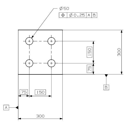
I like the Belanger example. I think this is pretty much what I'm after. See attached for my final drawing to achieve what I'm after. Does this look correct?


Hobbs101
Mechanical Design Engineer
 
 http://files.engineering.com/getfile.aspx?folder=07bd59dc-2448-4eac-9165-2904ceb8d3fa&file=central_holes.jpg
hobbs101:

Your drawing is correct. But I would add the center-plane lines to "remind" the reader of the datum center planes. Additionally, the 4 holes and Datums B and C are features of size (FOS), and with the lack of MMC symbols (RFS assumed by Rule #2), I was wondering if there was any consideration of material condition modifiers - MMC in particular.
 
hobbs101

The center-plane line look good. But I would not casually add MMC unless the design accepts "virtual condition" and "bonus" tolerance concepts.
 
Status
Not open for further replies.

Part and Inventory Search

Sponsor