Continue to Site

Eng-Tips is the largest engineering community on the Internet

Intelligent Work Forums for Engineering Professionals

  • Congratulations KootK on being selected by the Eng-Tips community for having the most helpful posts in the forums last week. Way to Go!

GD&T for circular pattern of open slot feature

Status
Not open for further replies.

newby81

Mechanical
Apr 23, 2015
14
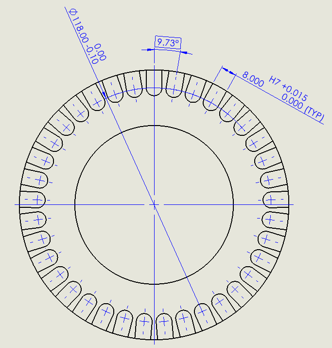
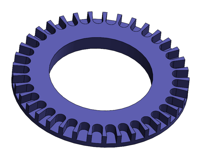
Any advise on this would be appreciated. I have a round object with a central hole. A slot is cut inwards from the outer edge. This feature is patterned around the disc (equally spaced).

The critical features are the width of the slot, the angle between slots (all instances must have identical angles)

I am not sure of the best GD&T control to use for this.

Thanks
Disc1_ctyrsp.png


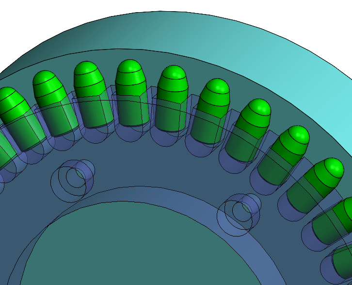
Disc2_dbmrow.png

 
Replies continue below

Recommended for you

ASME is what we usually work with.
 
And how this part is assembled with its mating components? What suppose to fit into those slots?
How critical is the radius on the bottom of those slots?
I know ........many questions, but if you need advice some details should be provided.
 
The actual manufactured part will not have equal angles. Nor will the slots have equal widths and none of the midplanes of the slots will be congruent with the any axis of any cylindrical feature on that part.

The questions to be answered for each of these is - how much variation from the ideal condition is tolerable?
 
Understood.
Steel pins will be retained in the slots thus the need for a tightly controlled slot width. The radius portion is not very critical as it just clearance round the end of the pin.

The depth of the slot feature is also probably critical as the bottom face of the slot will clamp against the diameter of the pin. The depth dimension itself does not have to be tightly controlled BUT all the slot depths need to be the same so that all pins are clamped in the final assembly.

Disc3_dnbrfm.png
 
newby81,

I would recommend position RFS to control the center planes of the slot widths. This will control the angle and spacing between the slots. Add datum features if you need the slots to be perpendicular to a particular face or centered on one of the diameters.

For the bottoms of the slots, I suggest composite profile, referencing the top face as the datum feature. The upper segment tolerance can be relatively large if you don't need the absolute depth to be very accurate. The lower segment tolerance should be tighter, to control the consistency of the depth.


Evan Janeshewski

Axymetrix Quality Engineering Inc.
 
In regards to radial location control:

Stopping an item with a tangent radius means that the consistency of insertion placement will be highly dependent on the slot width and on the mating item dimensions. It's the sort of fit that can easily be a self-locking taper.

I would cut a groove with the OD at the depth required and place a metal strip or wire roll formed to match the OD into the groove as the stop. Retention could be using a shaft locking compound.

The groove can have a total runout tolerance to the center of the rotation axis controlling surface.

Note this mating also needs to be controlled if the goal is uniform presentation.

 
As far as equal angled spacing - if that is for indexing, it's better to have a detent that indexes on the individual slot rather than depending on perfect control of the tangential location. With an insertion depth stop independent of the slot depth, the slot can be made deep enough to engage a detent.

I'm sure that's not what is desired here - but it's a common positioning element in other machines.
 
Status
Not open for further replies.

Part and Inventory Search

Sponsor