Eng-Tips is the largest engineering community on the Internet

Intelligent Work Forums for Engineering Professionals

GD&T for Threaded holes 6

Status
Not open for further replies.

Inund8_ca

Mechanical
Sep 23, 2022
9
0
0
CA
Hi all,
My coworkers and I can not agree on the proper GD&T for this situation:
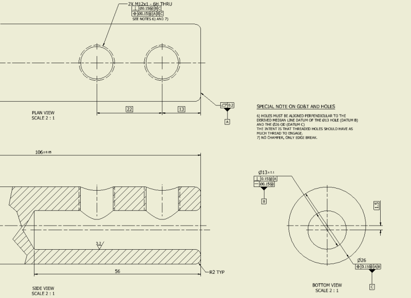
We have a shaft, with an offset blind hole in it. There are 2 threaded holes which run perpendicular to the hole. I need the GD&T to indicate that the set screw holes need to go through the thickest section of the part, otherwise the screws used here will fail in various ways.
Due to the constraints of the design, we cannot change the thread pitch of the screw holes.

This is what I have proposed, but I also feel at the same time that it's overkill. I'm also unsure if my perpendicularity callout on the threaded holes makes sense, since it references a derived median line datum, and a feature of size datum that is parallel to first.
And one colleague takes issue with the datum scheme, saying that the shaft should be the primary or secondary datum.
I'm curious to hear what solutions come to mind.
Screenshot_2023-06-15_084805_hweure.png
 
Replies continue below

Recommended for you

If the thread position is called out at MMC you'd have to use an MMC thread gauge to check the holes and the gauges would wiggle in the hole, making it impossible to know what you're really getting. Also, considering that the threads are helical wedges that complicates the checking method because you have to engage the threads at the pitch diameter. Having the note MINOR DIA under the feature control frame would've helped a little but I think the easiest is to use RFS. The RFS gauge would ensure you've accurately captured the axis of the thread. When using RFS you can just open up the positional tolerance some since you're not getting any bonus tolerance as with MMC.
 
Belanger said:
On the other hand, MMC/MMB is easier because a physical gage can be made at a single size (MMC/MMB).
The curveball with threads is that we don't feel any bonus or jiggle; the thread is engaged until it's finger-tight (or reaches a designated torque). But threads still have tolerance, so "M" on a thread is possible.

I never understood this whole reasoning for threaded holes at MMC.
If you control a feature of size at MMC the gage must be made at VC, not at MMC (unless the specified tolerance is 0 at MMC), so for a threaded hole what one has to apply? Is it needed to create a male thread with a pitch diameter smaller than the MMC pitch diameter for the hole by the amount of the stated geometric tolerance to check that the threaded hole does not violate it??? Sounds nonsensical. Besides, when VC gages are used for a pattern of two simple holes, they are of fixed size and fixed spacing. Since there are no special rules for cases when the holes are threaded, how does one apply the fixed spacing between the VC thread gages? Two threaded screws at fixed spacing to fit the two threaded holes over??? That's why I never specify tolerances at MMC for threaded holes.
RFS with a projected tolerance zone modifier allows the use of flexible thread location gages which makes much more sense to me both functionally and in terms of inspection practicability.
 
You can use the axis interpretation, not the surface interpretation, so the axis of the MMC threaded gage is what is controlled, same as when a position tolerance is larger than the feature MMC size.

Assembling a fastener with that additional clearance is a frequent occurrence, most notable when securing thin items where the projection is small.

In real world applications no one cares about pitch diameter location as the pitch diameter of the fastener will rarely match the pitch diameter of the mating thread. Instead one flank will be in face contact with the mating flank over 3-4 pitches at full tension, which RFS gauges never match anyway.

"how does one apply the fixed spacing between the VC thread gages?" Great question. I know how to make a gauge that checks the requirement the same way one would do for RFS pins.
 
Burunduk, in my thinking I was referring to a datum feature being threaded, where the "M" is called MMB. I only used the term MMC/MMB for those who might not be aware of the term MMB.
But to avoid reliving all the rabbit holes here, I suggest checking out the numerous discussions that I linked to. You might like the one entitled "RFS and Projected tolerance zone concept on threaded holes."

John-Paul Belanger
Certified Sr. GD&T Professional
Geometric Learning Systems
 
Axis interpretation, for a thread controlled at MMC, doesn't avoid a variable gage. Most advocates for MMC applied to threaded holes mention fixed size gages though.

The product in Season's link is one such variable gage. With this mechanism looks like it should be expensive enough to want to give up on the pitch diameter measurement and bonus calculation in favor of simpler devices.


Belanger, I think that referencing internal threads as a datum feature at MMB is workable for a single hole (also, only as long as it is primary). Assuming MINOR DIA is not invoked, using a pattern would create a problem.
 
Status
Not open for further replies.
Back
Top