Hello,
I currently work for a small company, and it has no acknowledgement of GD&T. I recently took an online course for GD&T, and I think it can help a lot in production because supervisors constantly get inspected parts that don't fit even though drawings meet specifications. I believe its the issue with plus and minus tolerancing without any bonus tolerances. So I want to solve the problem by including some GD&T for the company. Keep in mind I am still learning--in no way have I perfected GD&T.
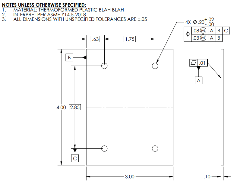
All images are mockups of parts--not exactly the parts due to proprietary reasons (obviously).
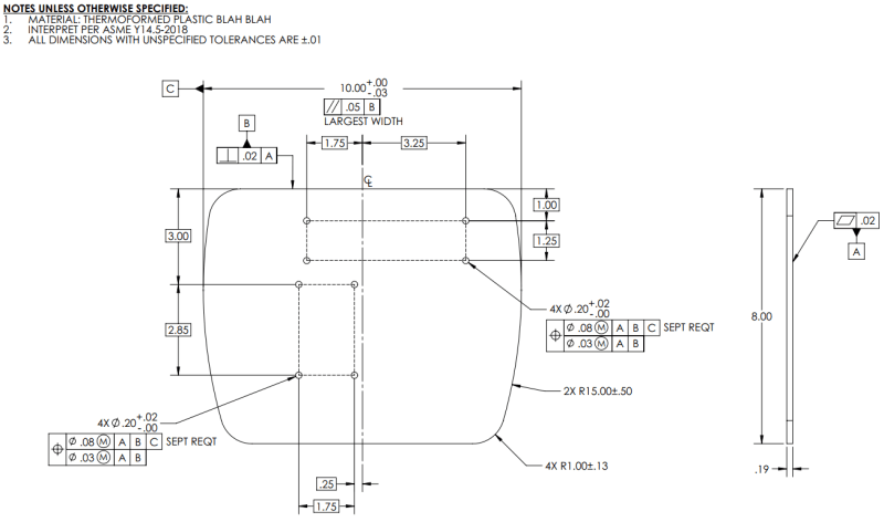
I have a rear cover/plate that is used to mount various subassemblies. The subassemblies are mounted by four holes in a rectangular pattern. I want to control the hole locations relative to each other, but I don't care too much about the overall placement of the hole pattern, so what I used was a composite position tolerance. Here is an image of the drawing.
Does this appear to be correct on what I am trying to do? Is there any issue with Datum Feature C? Would it be difficult to determine the center of the part due to the curve sides? I also read somewhere that if feature control frames have the same datum features, then the tolerancing is required simultaneously. Does that work in the drawing for both patterns? I don't want to have both patterns toleranced simultaneously; I want the two hole patterns to be independent from one another.
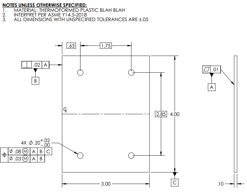
Since there is a mating issue. I also redid the mating assembly part. I just made sure the virtual condition equaled the hole pattern's virtual condition. Essentially, its the same tolerance as the cover.
This should ensure 100% fitment, right?
Thank you for anyone helping me out. I really do appreciate it!
EDIT 1: Fixed datum feature in image two. (2020-03-23 @ 7:23pm)
EDIT 2: Fixed feature control frame in image one. (2020-03-23 @ 7:59pm)
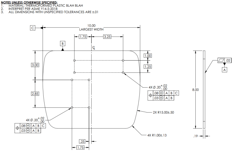
EDIT 3: Did not change original post to save change history. Edits to drawings have been made below that were suggested by Greenimi. (2020-03-24 @ 10:05am)
I currently work for a small company, and it has no acknowledgement of GD&T. I recently took an online course for GD&T, and I think it can help a lot in production because supervisors constantly get inspected parts that don't fit even though drawings meet specifications. I believe its the issue with plus and minus tolerancing without any bonus tolerances. So I want to solve the problem by including some GD&T for the company. Keep in mind I am still learning--in no way have I perfected GD&T.
All images are mockups of parts--not exactly the parts due to proprietary reasons (obviously).
I have a rear cover/plate that is used to mount various subassemblies. The subassemblies are mounted by four holes in a rectangular pattern. I want to control the hole locations relative to each other, but I don't care too much about the overall placement of the hole pattern, so what I used was a composite position tolerance. Here is an image of the drawing.
Does this appear to be correct on what I am trying to do? Is there any issue with Datum Feature C? Would it be difficult to determine the center of the part due to the curve sides? I also read somewhere that if feature control frames have the same datum features, then the tolerancing is required simultaneously. Does that work in the drawing for both patterns? I don't want to have both patterns toleranced simultaneously; I want the two hole patterns to be independent from one another.
Since there is a mating issue. I also redid the mating assembly part. I just made sure the virtual condition equaled the hole pattern's virtual condition. Essentially, its the same tolerance as the cover.
This should ensure 100% fitment, right?
Thank you for anyone helping me out. I really do appreciate it!
EDIT 1: Fixed datum feature in image two. (2020-03-23 @ 7:23pm)
EDIT 2: Fixed feature control frame in image one. (2020-03-23 @ 7:59pm)
EDIT 3: Did not change original post to save change history. Edits to drawings have been made below that were suggested by Greenimi. (2020-03-24 @ 10:05am)