Eng-Tips is the largest engineering community on the Internet

Intelligent Work Forums for Engineering Professionals

GD&T- profile tolerance and basic dimension 1

Status
Not open for further replies.

zsa

Mechanical
Dec 1, 2016
22
0
0
US
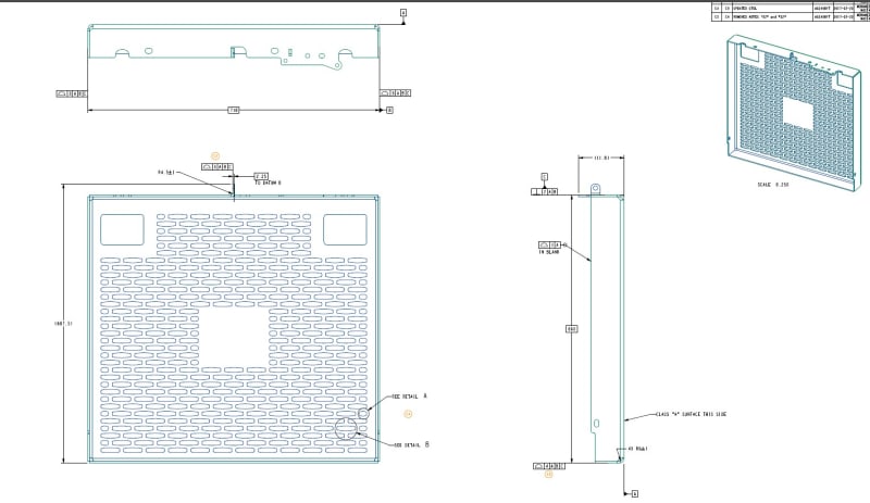
Attaching the print/drawing in question. In terms of the gd&t governing the basic dimensions for length and width of the box, I am not certain how to translate the gd&t into relatable plus minus tolerance for our shop floor. For the 718 basic dimension, I know that if only one end had the profile tolerance called out, I could translate that to a 718 +- 1.5 but with the profile called out on each end, what are my options here?

Likewise, on the 660 basic dimension, I believe the perpendicularity call out kind of acts like a profile in this case and so how do I deal with that dimension in terms of +- tolerances?

We will have our CMM guys in quality verify these parts as we go through the initial PPAP approval process but for long term production and the generation of our documents and check sheets etc, I need to translate this into a somewhat representative +- tolerance.

 
 https://files.engineering.com/getfile.aspx?folder=dce11398-b610-4e83-99cc-947ffca57abd&file=print_screenshot.jpg
Replies continue below

Recommended for you

You have a self-referencing feature frame--Datum B is measured to datum B. Not sure how that will play. Probably behave like a perpendicularity or flatness in this context.
 
zsa,

On a folded sheet metal platform, the folded edges are not accurate, so they make poor datum features. I strongly recommend picking a couple of holes as your secondary and tertiary datum features, then use profiles, sloppy ones, to control your flanges.

As TheTick notes, your secondary datum feature can be perpendicular to your primary feature, and that is it. As shown, it is a feature of size and it needs a tolerance, but see my remarks, above.

--
JHG
 
Hi, zsa:

Equivalent size tolerance of dimension 718 is +/- 3mm. But you are not supposed to assess this feature of size as it is not a specification on the print.

Hi, TheTick:

I don't see "You have a self-referencing feature frame--Datum B is measured to datum B". The datums on this print seem robust.

It would be good if Datum A is refined with a flatness control. I agree datum feature B need to have a perpendicularity control.

Best regards,

Alex
 
Right, jassco. I misinterpreted. "B" is the center plane of the two side flanges.

Either way, I don't like it. Definitely not going to help with process control.

I would try to exploit features on the "A" face for additional orientation control (i.e. datums "B" and "C"). Those rectangular holes look like nice possibilities.

print_screenshot_epefi3.jpg
 
Thanks everyone for the reply!

@jassco, I understand that the width is a feature of size that is not directly on the print but it is a basic dimension which is then driven by the profile callouts on each end- technically if I have a part that is good on all counts but the width is 722 that part is ‘bad’, correct?

Also, can I assume the same principle applies for the 660 basic dimension? 660 +-3 (+-2 from the 4 mm profile and +-1 from the perpendicularity?)


zsa,
Why do you "translate" geometric tolerances to +/- tolerances? Do you always do it?
If it's for the shop floor, depending on the measurement equipment, there are various ways to generate reports that include useful data for in-process adjustments.
You mentioned CMM. There are CMM software packages that can generate color maps with numerical values of surface deviations that make it easy to see how the process needs to be corrected for features to conform to the tolerances.
 
Burunduk,

Our process requires a check sheet with some form of tangible measurements that operators can pull to determine if a part is suspected to be bad or if it isis OK. It is just a requirement of our automotive manufacturing process. They require a certain frequency of check like first piece, last piece and hourly checks of dimensions. For some parts, like the print in question, there are no 'direct' dimensions called out to measure, so we have to 'translate' the gd&t into something our shop floor operators can understand and implement. We still have the CMM but that is not used for regular production runs
 
It looks like the corners have to fit closely and there is a tight limit on the flat pattern profile, so unless it's really damaged then set a maximum gap at the corners. Since this isn't the only piece of sheet metal then the flat pattern should have been inspected by camera for compliance before getting here.

Likewise the top edges should match at the corners after bending.

I doubt that the part can be bent too small as that will ruin the corners/force metal into interference.

You can certainly use a 2-point measurement to reject some parts, but it won't necessarily indicate the parts are acceptable and it might reject acceptable parts.

I'm more surprised that there aren't tolerances on the features that look to me are critical to mounting the part.

Were it up to me, I would measure a few dozen of them, send them through to detailed inspection, and see if there are any rejects. If not, then I would determine the mean and standard deviation for the sample and set a measurement limit of 2 deviations. Do a sample of parts in detailed inspection and update the in-process limits based on acceptance.

If the corners are getting closed and the top edges are even, then there is little chance of unacceptable parts getting through leaving the in-process inspection for a dimension value a general waste of time.
 
Hi, zsa:

Yes. A part with 722 would be a bad one. The same principle applies to dim. 660 BASIC.

Also, you will need simultaneous requirements for all the cutouts. Because datums are not accurate enough to define each individual cutout (slots and rectangle holes), you will need to define them with the same datum sequences so all the cuts are made and inspected with a single setup.

Best regards,

Alex
 
Status
Not open for further replies.
Back
Top