Continue to Site

Eng-Tips is the largest engineering community on the Internet

Intelligent Work Forums for Engineering Professionals

  • Congratulations SSS148 on being selected by the Eng-Tips community for having the most helpful posts in the forums last week. Way to Go!

GD&T question about concentric holes

Status
Not open for further replies.

aammons2

Mechanical
Dec 5, 2022
2
Hello,

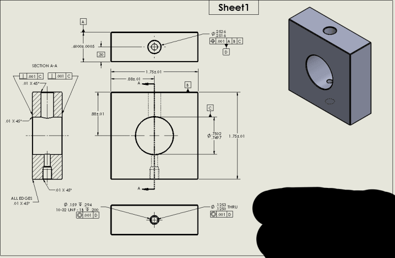
I was hoping to get some guidance with GD&T as this is my first crack at it out of school. This is a gage that will have a precision ground pin coming in from the top to check for a hole location in a cylindrical part w.r.t a dimple on the bottom side of that part. Hole and dimple are in line with one another. Have I called these out properly? Both the top hole in the gage w.r.t datums A, B, C and the hole in the bottom of the gage that I want to be concentric with the top hole.

Thank You

tempsnip222_lzp5nu.png
 
Replies continue below

Recommended for you

Based on your description, sounds like the 10-32 UNF hole should be toleranced for position with ref. to datum feature A (.75 diameter), and then designated as datum feature B. The .25 diameter hole should be toleranced with ref. to datum feature A as primary and datum feature B as secondary. A and B would constrain all 6 degrees of freedom.

Is the external cylinder of the mating part that fits in the .75 hole used as a datum feature referenced at MMB for that part? If not, technically you're supposed to use a contracting adjustable diameter as the datum feature simulator on that gage. I don't know what your tolerance is for that diameter (you show the same number for upper and lower limit) but whatever tolerance you will end up specifying may give you an unintended datum shift.

There are other issues there to address, but, I would focus on the above first.
 
Typically (and required) for Feature control frames/positional geometric tolerance the locating dimensions are basic and, where applicable, are between the controlled feature and the datum feature.

In other words 27+/-.00 should have no tolerance (though .00 is a challenge) and should include datum feature B as the reference surface.

Since the hole are round and the feature control is on the diameter of the holes, the position tolerance should have the diameter symbol.

I would probably use the same references for the threaded hole as for the gauge pin hole so there is a simultaneous requirement for them both. Your machinist and the inspector will like avoiding an additional set-up.

 
I prefer to use planes as primary datums because 90% of the time the measuring equipment has a flat table.
Holes shall have tolerance. You'll make someone angry if you require .000 dimensions.
 
Okay, after making some revisions and correcting the tolerance issues here is what I have arrived at.
Thanks for the pointers. I think this is much better. Any suggestions?
tempsnip_zgrtgr.png
 
What dimensioning and tolerancing standard are you using?
If you are working per ASME Y14.5 avoid the Concentricity tolerance. It is a complex control that doesn't provide any advantage over other geometric characteristics that can achieve coaxiality, and it was removed from the standard in its latest edition (2018).
If you are referencing datum features A, B, C as primary, secondary and tertiary, in that order, to locate the top hole, specify for datum feature B a perpendicularity tolerance with ref to A, and for datum feature C a position tolerance with ref to A primary, B secondary. This is needed to qualify the datum features.
If you do the above, Perpendicularity control of each face of datum feature of size A relative to datum C will not be needed.

Other than that, you don't need a basic dimension of 30 from one of the faces of datum feature A to show that the top hole is centered to it. Instead, show a center line representing the center plane coincident with the cross at the center of the hole. Basic zero distance (coincidence) will be implied per the Fundamental Rules of the standard.

Place a diameter symbol before the geometric tolerance value whenever controlling an axis of a hole (or pin).
 
Also, as I already mentioned in my first response:
Referencing the large hole in which the OD of the mating part will fit as the primary datum feature and the threaded hole for the device that will mate with the "dimple" as the secondary datum feature for the position tolerance of the top hole seems like a more suitable solution for the function of the part as you described it. The datum features will have to be qualified relative to each other accordingly.
 
Also avoid using very tight dimensional tolerances. Apply flatness for required surfaces and you'll end up with a much friendly size tolerance. (in this case I assume the thickness tolerance is not required because the flatness does not take action in the gauging process)

Here's my take on this: (dimensions are metric and not necessarily represent your part, but the concept is the same)
suggest_vit9bw.png
 
Status
Not open for further replies.

Part and Inventory Search

Sponsor