Continue to Site

Eng-Tips is the largest engineering community on the Internet

Intelligent Work Forums for Engineering Professionals

  • Congratulations cowski on being selected by the Eng-Tips community for having the most helpful posts in the forums last week. Way to Go!

GD&T question 5

Status
Not open for further replies.

lwh723

Mechanical
Mar 1, 2016
4
Hi,

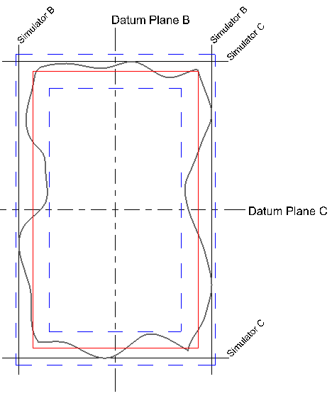
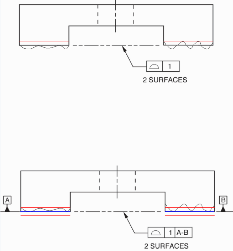
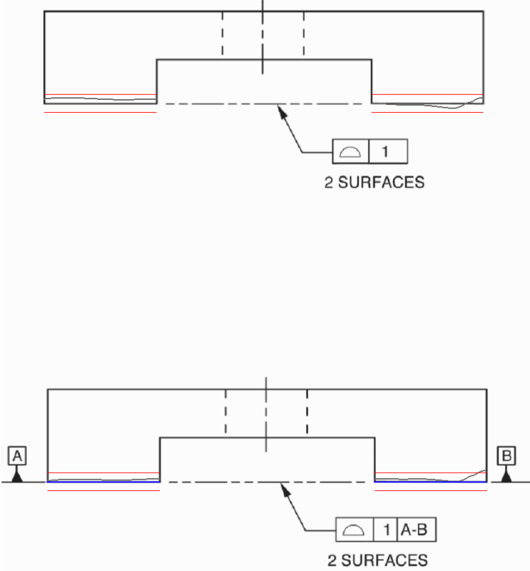
So hoping some experts can help me put a question to bed. I work in the electronics industry, so really don't need to use GD&T at all. However, our data sheet drawing has this call out, and it's been the source of much debate with some customers. I've attached a picture of how I understand it, but some customers are taking it to mean that the 0.1 profile zone encompasses the B & C edges of the part. But those are datums, so shouldn't be included, right? In general, I think it's just a poorly done, but that's another issue.

 
 http://files.engineering.com/getfile.aspx?folder=d2f42e22-e671-4c63-8243-8678066fd906&file=drawing.pdf
Replies continue below

Recommended for you

pmarc - why would only half be available? There are some difficulties with making a feature's location tolerance self-referential, but I don't see half. The references locate the midplanes that are the origin of the tolerance zone so they cannot influence the size of the tolerance zone. Since the zone is unaffected, the orientation limits are unaffected.

What I think it would do is reject a certain number of parts that are as usable as parts that are accepted.
 
JP,

I don't perceive any difference in interpretation between your first picture and your second.

John Acosta, GDTP Senior Level
Manufacturing Engineering Tech
 
pmarc,

Okay, you got me on this one. You're absolutely right, I hadn't thought of irregular features of size at all. Basic widths and profile are used with those, the examples clearly show it. I'm not a big fan of the irregular features of size section - I don't think the definitions are very clear. Perhaps this is why I didn't think of it - it never entered my mind to apply the "irregular" concept to a feature that has "regular" geometry (two opposed parallel planes). This does not seem very intuitive to me at all, and must be very confusing to those who don't obsess over the Y14.5 standard like we do.

But I would disagree with the interpretation of the zone availability. If B and C are treated as features of size with centerplane datums, then I would say that the entire zone thickness is available for the B and C surfaces. Like this:

AllAroundProfileCenterplanes_sly5iu.png


So the form of the B and C surfaces, and maximum angular error between them, is the same as it would be if only A was referenced (or no datum features).

I would agree that specifying the B and C datum features does make a difference. Aligning the profile zone to the two B surfaces will be different than best-fitting it to the four surfaces together. This will need a different figure though.

Evan Janeshewski

Axymetrix Quality Engineering Inc.
 
powerhound -- see pmarc's reply and lemme know what you think.

And everyone should keep in mind that the OP's question was about the datums being derived from a FOS. My sketch was about a surface datum. (Sorry if that introduced any confusion, but my sketch is related to a real design I'm working on, and I figured they are somewhat related topics.)

I think the bottom line is that good practice deems that a profile tolerance shouldn't reference a datum that is derived from a surface lying within the profile coverage.

John-Paul Belanger
Certified Sr. GD&T Professional
Geometric Learning Systems
 
I read pmarc's reply but since Dave asked for an explanation I was kind of waiting on that. That being said, I do see what pmarc is saying. Since the profile tolerance specifically calls for a tolerance zone equally disposed about the datum plane, only half (to the inside) would be available since the datum simulator would take up the other half. This means that I agree with pmarc and rescind my previous comment on the drawing.

John Acosta, GDTP Senior Level
Manufacturing Engineering Tech
 
Evan,
I got you on one, you and 3DDave got me on the other. I was too hasty with my reply to Dave. Thank you for being cautious and critical.
 
Okay, just to be sure, my response was in regard to JPs drawing, not to the OP.

John Acosta, GDTP Senior Level
Manufacturing Engineering Tech
 
J-P and All,

Here is how I would envision the situation for the coplanar surfaces:

Coplanars2_gtixmp.png


I've shown the same as-produced surface geometry for both cases. When no datum feature is referenced, the surfaces can occupy any part of the zones and the control is equivalent to coplanarity. When the A-B datum feature is referenced, the surfaces must have high-point contact on simulators located at the basic surfaces.

I believe that this is fully consistent with pmarc's description.

Evan Janeshewski

Axymetrix Quality Engineering Inc.
 
Thanks -- that's how I envision it too. The situation I'm dealing with had the typical A, B, C, edge datums (with no GD&T relating those features to each other), and then a general note imposing profile of a surface 3 mm everywhere unless otherwise specified. Thus you all can see the problem; half of that profile tolerance is lost on the surfaces creating the datums.
I keep telling them about it, and suggesting that they "qualify" A, B, and C (flatness on A, perp on B, etc.) so that those surfaces are exempted from the general profile note. We'll see if it goes anywhere.

John-Paul Belanger
Certified Sr. GD&T Professional
Geometric Learning Systems
 
Sorry for stupid question, but is "general note" specifying profile to A|B|C, or just "profile"?

"For every expert there is an equal and opposite expert"
Arthur C. Clarke Profiles of the future

 
I have often seen similar "profile of a surface all over" general notes in the past, and also agree that half of the tolerance is unusable on the datum features.

The "profile of a surface all over unless otherwise specified" usage brings up another question in my mind though. Does flatness, perpendicularity, angularity, or anything other than profile of a surface count as "otherwise specified", or is a different profile of a surface tolerance with an identical DRF required? I'd lean towards the latter, because anything else could be intended as a refinement or supplement to the general profile of a surface all over. Other opinions on this?

- pylfrm
 
Evan, I don't think there's a real difference between our points of view regarding JPs first drawing. The zone still extends from the high points inwards with a coplanar type callout. It would be the same if the coplanar features were then referenced as datum features. I think the only way a tolerance zone is actually centered about a true profile is when the scenario is as JPs second drawing--although only half the zone is available, and when the features are actually toleranced from a datum reference frame and not used as datum features at all.

John Acosta, GDTP Senior Level
Manufacturing Engineering Tech
 
Sorry CH -- yes, the general profile of 3 that I mentioned was referenced to A|B|C

John-Paul Belanger
Certified Sr. GD&T Professional
Geometric Learning Systems
 
Evan, if you made the profile unequal you could have anywhere from no tolerance to all the designated tolerance.
 
It's actually even more interesting, because it depends on the process you use to establish the datum.
If you use hard gage to establish "highest points" datum, then only half of the tolerance is usable on the datum features.
If you "average" your CMM measurements, the entire tolerance is available.

"For every expert there is an equal and opposite expert"
Arthur C. Clarke Profiles of the future

 
After this entire conundrum, should the average GD&T user conclude that:
In case of a rectangle specified with profile, as a general note, to A, B and C:

If the datum feature is the center plane (B and C) of the part then the full profile tolerance is available.
If the datum feature is the surface (right vertical surface OR left vertical surface for datum feature B; top horizontal surface OR bottom horizontal surface for datum feature C) then only half tolerance is available.


Please kindly advise.
 
Ch,

Could you explain what you mean by:
"If you use hard gage to establish "highest points" datum, then only half of the tolerance is usable on the datum features.
If you "average" your CMM measurements, the entire tolerance is available"

Why if you are using LSQ method on CMM then the entire tolerance is available?
 
pylfrm,

That's a good question. I would think that the general tolerance would apply to everything, and then other tolerances would be refinements that would apply in addition to it.

powerhound,

It sounds like there is still a difference in our points of view. I'm saying that the tolerance zone is centered about the true profile in both cases. I don't see the zone extending from the high points inwards in either case. Please see the additional example below. Here is the logic:

1. The tolerance zones have basic location (centered about the true profile).

2a. If no datum feature is referenced, the toleranced features can be simultaneously fitted (rotated and translated) relative to the zones to get the best result.

2b. If datum features are referenced, the datum feature surfaces must contact the datum feature simulators at their high points. The datum feature simulators are coincident with the true profile.

3DDave,

Yes, if the profile tolerance was SPF|1(U)0|A-B| then there would be no usable tolerance. Interesting.

CH,

You're correct, but the method used to establish the datum is not open to interpretation. The default is high-point contact with a perfect simulator. If an averaged plane (such as least squares) is used, then the rules are not being followed. This is a big issue with CMM's.

greenimi,

I believe that you're correct. If the B and C datum features are width features with centerplane datums, then the entire profile tolerance is available for the B and C surfaces. If the B and C datum features are each single planar surfaces, then only half the profile tolerance is available for the B and C surfaces. Strange, isn't it?

Here's another example:

Coplanars3_qied5k.png


Evan Janeshewski

Axymetrix Quality Engineering Inc.
 
axym said:
Yes, if the profile tolerance was SPF|1(U)0|A-B| then there would be no usable tolerance. Interesting.

Evan, I think you meant SPF|1(U)1|A-B|.
 
pylfrm said:
The "profile of a surface all over unless otherwise specified" usage brings up another question in my mind though. Does flatness, perpendicularity, angularity, or anything other than profile of a surface count as "otherwise specified", or is a different profile of a surface tolerance with an identical DRF required? I'd lean towards the latter, because anything else could be intended as a refinement or supplement to the general profile of a surface all over. Other opinions on this?

From the Y14.41-2012 "Digital Product Definition Data Practices" (future version of the Y14.5 will have very similar paragraph):
"1.3.10 Unless Otherwise Specified (UOS)
The phrase “unless otherwise specified” or UOS is used to indicate a default requirement. The phrase is used when the default is a generally applied requirement and the exception can be clarified by providing a reference to another document or requirement."


To me 'the exception' means that anything other than the general profile tolerance overrides that general profile tolerance.
 
Status
Not open for further replies.

Part and Inventory Search

Sponsor