Eng-Tips is the largest engineering community on the Internet

Intelligent Work Forums for Engineering Professionals

GD&T question

Status
Not open for further replies.

banshee1

Automotive
Mar 5, 2014
24
0
0
US
So QC and myself have been discussing the inspection of a part (attached a copy of our in-process print).
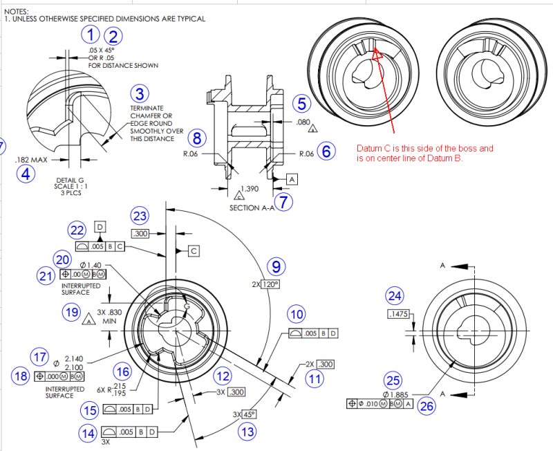
QC says that to inspect the part, they origin of Datum B (an OD), square up to Datum A (face of part), then take a hit on Datum C surface. They then rotate thru that point to create an alignment. Next they measure Datum D (they use one point on approx. center of that surface), then create a point .300 from where Datum D measures (call it point 4). Next they rotate thru point 4 for alignment. To inspect the same surface on the next lobe they rotate 120º from that new alignment and measure that surface and expect to see .300, then rotate another 120º and measure the same side of the next lobe.

Does this make sense or right?

I say this is wrong. I don't think he should be creating point 4 and re-aligning thru it. To me it seems like it would compound any error.

I would appreciate any insight anybody has on this. Sometimes this GD&T just makes my head hurt.


 https://files.engineering.com/getfile.aspx?folder=6bcaedf1-6db6-4474-93f7-7c603f3fc4eb&file=GD&T.pdf
Replies continue below

Recommended for you

My head hurts too just from looking at this drawing. I apologize if you were the one who drew this, but it seems to be drawn in the most convoluted manner possible.

As 3DDave stated your attachment link/name may not include the "&" symbol and causes issues. By adding "%26T.pdf" at the end I was able to download your file. Not that small snapshots like this can also be added directly into the body of your post with the "upload image" button.


Several issues/questions with your print:

1) What standard is your drawing compliant to? I assume Y14.5 judging by the notation, if so what year?
2) What is the OD which is datum feature B? Typically I wouldn't be concerned, but judging by the way the drawing is executed I am inclined to ask.
3) A is not included in any of the FCF's shown. Even if A is utilized to establish B (I can only assume - it is not shown), A is not involved when measuring to |B|, |B|C|, or |B|D|.
4) You referenced "datum C surface" - first this would be a datum feature, and secondly it sure looks like the datum feature symbol C is attached to a center line which is invalid. Your datum features must be actual physical features on your part (planar surface, diameter, width, etc..) even if the datums derived from them are theoretical. One cannot take a measurement from datum feature C since it does not exist - not sure how your QC team planned on taking a measurement from a theoretical center line/plane, unless theres a surface that I'm not seeing.
5) That said, the datum feature D could just be controlled with profile to |B| - even though I doubt singling out one of these surfaces alone really reflects function. I assume this is some sort of trunnion/CV joint and all 6X are bearing surfaces for the mating tripod - seems to me they should be controlled together with profile to |B|.
6) The 3X .830 MIN to a tangent point on a radius is a dubious specification. I guess the intent is to try and guarantee a minimum length of the bearing surface - while I'm not sure of a better way to do this I can almost guarantee that measuring a reliable point of tangency is going to be troublesome endeavor.
7) Assuming you are going by Y14.5-2009+ there is already an established mechanism instead of notating "interrupted surface" - this is the continuous feature symbol <CF>.
8) Keeping in mind (5) and (7) I'm left to wonder if all around profile with refinements for the bearing surfaces wouldn't be a much better specification than attempting to evaluate size of features with very few (or zero - in the case of the ID) opposed points. One would lose the advantage of MMC, but gain a much more robust specification as well as simplify measurement. In any case control of all 6X bearing surfaces simultaneously as noted in (5) is definitely a strong recommendation.
 
I just spent some time simulating his process in my CADCAM program, and maybe what he is doing is right, and I just couldn't grasp it in my head without drawing it out. I was thinking that once he meas./found Datum D he could call that "zero" per say, then rotate 120º from the original alignment (thru C) to measure the next surface. Now that the cmm is "offset" whatever Datum D measured from the original alignment, when he measures the next surface he should see/measure 0.0 +/-.0025 (for profile of .005). Maybe it's because of the 2x.300 callout he's doing it the way he is.

The one thing still throwing me is Datum D. Lets assume Datum D measures at a slight angle (say .15º and at the midpoint of that surface it measures .300), how do you translate that to the other surfaces? Or should/do you? If the same side on the next lobe is rotated the same .15º but in the other direction that surface would be right at the .005 profile tolerance if you maintained the orientation of Datum D. However if you assume Datum D is parallel to Datum C and you rotate to measure the next lobe, the cmm would only report a profile of .0006 leading you to believe that surface is near perfect.

Maybe I'm just over complicating things, misunderstanding something, or maybe I'm adding things that just wont come in to play.

 
See my (4) and (5) above. C doesn't seem like a valid datum feature and it seems all 6X bearing surfaces should be controlled together. If only one surface is specified datum feature D then the remaining 5X profile tolerance zones for the other bearing surfaces are clocked relative to D.
 
1st, sorry about the link not being correct. This is how the think was inserted by the attachment option.

Chez311, this is an inprocess print created by our manufacturing engineer, however it is exactly as it is shown on the customers supplied print. Yeah it's a mess.

1) Customers print does not specify, however I believe it is Y14.5, and it was originally drawn in 2012.
2 & 3) Datum A is a face on the part and B is a 2.3115 diameter and both are used to establish the center line/axis of the part.
4) Datum C is the side of a feature on the other end of the part. And it is on the center line of the part.
5) My answer to question 4 will probably help answer this.
6) Yeah, we struggle with this every time we machine these parts and we've done 6-8 different runs at least.

I don't know what the mating part is or looks like as we haven't made one, nor have we quoted it. It might explain a lot of why they dimensioned it the way they did. And going back to this customer to get it clarified or re-drawn to make more sense would be an act of god.

Again I appologize for the link and not showing you the entire print. Because I know the parts and such I knew what was what and what didn't apply so I omitted them, but none of you know that so that's my bad.

Appreciate all the insight guys!
 
No worries about the link - its a common issue with new posts.

And going back to this customer to get it clarified or re-drawn to make more sense would be an act of god.

And manufacturing/measuring a part that is not properly specified is like playing darts while blindfolded. Maybe not an act of god, but certainly difficult.

1) This must be known in order to properly inspect the part. You might as well inspect the part however you like if the standard is not specified.
3) Even if A is utilized to establish the tolerance zone for B, if your FCF only utilizes |B|, |B|C|, or |B|D| it is NOT involved in establishing a tolerance zone with those DRF's that do not directly include A. If |A|B| were specified (its not anywhere on the snapshot you sent - but lets say it was) then A would constrain (z,u,v) and B would constrain (x,y). When |B|, |B|C|, or |B|D| are specified - as they are on your drawing - then B constrains (x,y,u,v) in all three cases. A is not involved.
4) Y14.5 specifically prohibits attaching a datum feature symbol to a center line/plane as shown. This is not a "maybe" or "not recommended" - it is not allowed. Any feature which is either coincident with this center line/plane or who has an axis/center plane which is coincident with it could be misconstrued as being the feature from which the datum is derived. Technically any drawing that contains such notation is noncompliant according to Y14.5 and should be sent back for revision.
Y14.5-2009 said:
4.8.2 Datum Feature Identification
Datum features are identified on the drawing by means of a datum feature symbol. See Figs. 3-2, 3-3, and 3-4. The datum feature symbol identifies physical features and shall not be applied to center lines, center planes, or axes.

5) It would, if datum feature symbol C were properly applied.
 
Datum feature symbol C may be properly applied. It appears to be attached to the dimension extension line. A better section, such as from a view projected up from this view would show both the datum feature and the associated feature dimension and make clear the relationship. This is a frequent problem when dealing with multiple coincident features.

Any setup that uses some reference other than those specifically called out in the FCFs should not be done.

Given the FCFs it takes 6 hits minimum on the cylinder for datum feature B and 2 hits for datum feature C.

Same thing for [B|D] - 6 and 2. One hit on the secondary is not enough to correctly align the part when the nominal plane is not passing through the primary feature axis.
 
3DDave,

I guess one could argue it is applied to the dimension extension line and not the center line - fair enough. Though without the datum feature of interest visible in the view shown, it looks to an outside observer that the datum feature symbol (as well as the .300 basic dimension) is applied to the axis. Perhaps the intent was to apply it to some feature coincident with the axis, but we do not know that looking at the drawing.
 
I tried edit my original post with a new link for a png file of our full in process print but it won't let me and it wouldn't let me add it to the body so here it is. I added clarification on what Datum C is.

Chez, I'm trying to find the p.o. as the spec is sometimes included on this customers p.o. Well no luck there either. Maybe we have it on file somewhere, but lets assume (I know, I know) it's Y14.5.

Dave, so from what I understand you're saying once the cmm is aligned thru Datum C, it would check Datum D using the .300 basic. Now how should the cmm program be written/processed to inspect the rest of the lobes? To me the creation of a point .300 from where the cmm measured Datum D, creating a new alignment from center of Datum B thru that new point and rotating 120º and 45º from there is wrong. I believe the alignment the cmm used to inspect D (lets call it alignment X) should stay, then the cmm would rotate 120º, measure the next .300 basic dim. (bubble 11), then offset parallel the value Datum D measured from alignment thru Datum C, call that "zero" (call it say alignment Y) and measure that lobe. Then the cmm should pick alignment X back up and rotate to the next surface and repeat. This would give you a direct profile variance of that lobe face from Datum D. Do the .300 basic's (bubble 11 and 12) have to be reported/recorded back to the customer in normal circumstances?

The problem we're having is that unless Datum D is perfectly .300 from Datum C, the cmm is skewing the results of the remaining lobes. I proved it yesterday when I had him create a new program, this time instead of creating the new point exactly .300 from where Datum D measured and rotating thru it, he created the new point what the cmm measured Datum D to be off (basically leaving it at the original alignment X), then inspected the rest of the lobe surfaces. It showed all 6 lobes to have roughly the same amount of stock on. Which it should as the machine program was done with everything at nominal. I understand machines don't always do what you tell them, but this machine has always been very accurate.

Thanks guys.


Capture_dv4jrk.png
 
The part must be realigned to check the other lobes. They don't refer to [C] so there is no alignment to [C] that should be done for them. If the FCFs said [B|C] then you would use that, but they don't.
 
The problem we're having is that unless Datum D is perfectly .300 from Datum C, the cmm is skewing the results of the remaining lobes.

Of course it will. Thats what is dictated by the profile tolerance as it is written - whether or not thats whats actually desired. Instead of 6X profile tolerances held together to |B|C|, which if I'm to take a guess would more likely reflect function, you have 1X profile tolerance to |B|C| establishing D and 5X to |B|D|. Wherever datum feature D comes in at relative to |B|C| will affect the clocking/alignment of the remaining 5X profile tolerances.
 
Dave and Chez, you guys are probably thinking I'm an idiot to keep badgering you on this, but I struggle with some GD&T and how to properly apply/use it in certain conditions like this one. There's a reason why I'm on the productions side of a part and not the inspection side.

I understand what you guys are saying, but if what you say is true Dave, is the method the inspector/cmm is using the correct way to align the machine to Datum D? To make things easier for myself to explain/understand and lets assume the Y axis of the cmm represents the alignment thru Datum C which again we'll assume to be perfect to make things less complicated for me hopefully. If Datum D is not parallel to Datum C as it's dimensioned/shown on the print, you have to rotate the Y axis (about Datum B) so it is as parallel to Datum D as possible correct? Lets call this alignment D. Now because the 120º angle is a basic and dimensioned from Datum D, you would rotate the cmm 120º CW from alignment D about Datum B (which is the centerline of the part) regardless of how far Datum D deviated from Datum C (as long as it measured w/in the .005 profile tolerance) right? Now the cmm would measure this surface and would report deviations of this face as 0 +/-.0025 correct? To report the .300 basic from centerline (per bubble 11) the cmm would create a new line based on two hits on the surface and project that line thru center and calculate how far that line is from the center line of B correct? Now still on alignment D the cmm would rotate 120º CCW and repeat the same process of measuring that surface and projecting a line thru center and we'll call this alignment Z. To measure the other side of the lobes (still using alignment D), would you mirror/flip the Y axis, rotate 45º and measure the surface which I think would still be reported as 0 +/-.0025? Then as long as the furthest point is less then .0025 from nominal it would meet the profile tolerance. To get the .300 basic dim you create a line from the 2 hits on that surface and project it thru center and calculate how far it's off correct?

The problem we have with the current method of inspection (as explained in my 1st post) is that if the tool wears causing Datum D to be .299 and the cmm creating a point .300 from that and aligning thru it, it shows the corresponding face of the other 2 lobes as being .300 from centerline, but when it measures the opposing faces (45º) it says they are at .298. The only way to put those faces back to .300 I would have to create a new program for the machine tool and offset those 3 faces .002 Granted at .298 we'd still be w/in our .005 profile tolerance, but not by much. The operators only have a method of measuring either the Ø1.40 or Ø2.1/2.14 dia's and they have a lot of tolerance, but because of the profile tolerance they don't have anywhere near that tolerance. Production wise it's not feasible to keep adjusting the program, so we would have to have the operators keep the dia's to +/-.001 to be able to maintain the .005 profile tolerance with our current inspection method of those lobes. That's not accounting for if the tool develops a taper.

Chez, I would agree that the customer is likely just trying to maintain a .005 profile of each face back to |B|C|, and the engineer who drew this print probably didn't realize the way he drew it makes it difficult to manufacture.

Again, sorry for being thick headed and hopefully you guys aren't rolling your eyes back to far on this.

Thanks.
 
Status
Not open for further replies.
Back
Top