Eng-Tips is the largest engineering community on the Internet

Intelligent Work Forums for Engineering Professionals

GD&T Question

Status
Not open for further replies.

Qcprick63

Industrial
Mar 7, 2023
34
0
0
US
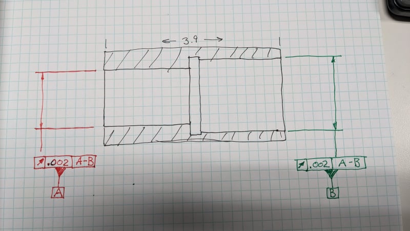
Not a fan of this type of callout.
I ran a circle at the far edges of both bores then recalled into a 3d line . Put a few more circles on both diameters and asked for runout back to the 3D line. I guess I report the highest runout value? Is that correct or is there a better way??
PXL_20240314_112714492_002_gp2wzs.jpg
 
Replies continue below

Recommended for you

In theory you shouldn't just take a circle at each end. The datum axis should be constructed from fully expanding inside the two bores. In a physical type of inspection I know that might cause issues because you are covering up the very surfaces that you're trying to measure for runout.
But once the common datum axis A-B is created, yes you would be looking for the highest runout error in each bore to report on the inspection sheet.
 
Qcprick63,

Is this your drawing or someone else's?

If you apply a diameter plus minus some accurate tolerance, the diameter is forced to be round. If that is not good enough, you can call up roundness explicitly. The feature control frames on your drawing make no sense to me.

--
JHG
 
Well, I asked around to several different forums, and it seems to satisfy this weird callout I am checking both bores with three circles each and combining them into a "stepped cylinder" that makes it one feature. then checking each circles runout to the Stepped cylinder. I don't like how this is being done but I have no other suggestions that make sense.
 
Hi, Qcprick63:

The feature control frames on your sketch are correct per ASME Y14.5 - 2018 (see Fig 7-17 on page 102 if you have a copy). If you have a CMM, you can inspect them easily.

The datum feature (A-B) in your datum control frame is called "Combined datum features" in ASME Y14.5 - 2018 if I remember correctly. In 2009 version, I believe it was named as "Multiple datum features".

Best regards,

Alex

 
jassco,

I have no objections to the combined datum features. I do this frequently.

The two diameters need to be tested separately for diameter and roundness. Combined, they create a datum feature for inspecting everything else.

--
JHG
 
3DDave said:
I would like to see the stress analysis that supports those tolerances and the datum feature reference selection.

May I ask how you would reference the datum features in this or similar cases?
 
You may ask, but since a part by itself is useless, I would need to see the rest of the system to see what an appropriate control would be.

My interpretation of this scheme is that two mating shafts are held in perfect rigid alignment with simultaneously expanding internal collets on the ends but I have no idea why circular runout would matter in that case instead of total runout. That's where I wonder why 0.002 is a limit and not 0.003. How did that cutoff come about? Is there a stress analysis to show that full contact can still be made if 0.002 variation is found in the part? Or did they want 0.000 and 0.002 was the best their supplier can do?
 
Status
Not open for further replies.
Back
Top