Eng-Tips is the largest engineering community on the Internet

Intelligent Work Forums for Engineering Professionals

  • Congratulations waross on being selected by the Tek-Tips community for having the most helpful posts in the forums last week. Way to Go!

GD&T scheme to control amount of twist in rectangular prismatic shapes?

Status
Not open for further replies.

mmolt

Mechanical
Jul 13, 2004
37
0
0
US
Hello all, I'm hoping you can help me determine a reasonable strategy to control the amount of allowable twist in a rectangular prismatic shape?

If you look at the following picture, I sometimes deal with the types of parts that can have twist induced by various means of manufacturing. This is the type of twist that can be recognized by putting the part on a granite slab, and noticing one corner of the part will rise up from the slab when it's opposite diagonal corner is pushed down to contact the slab. In fact, it's quite practical for us to measure this twist by inserting feeler gauges into the gap between the slab and the rising corner. So we have a reasonable way to check and measure this condition, I'm just looking for advice on datum placement and feature control designation. Perhaps parallelism?
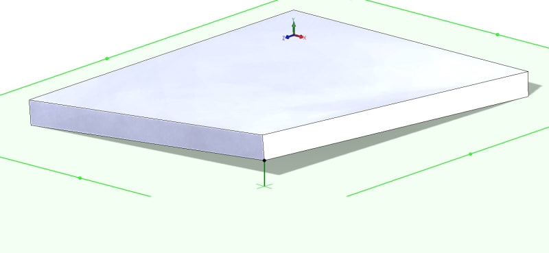
twisted_rect_prism_pvvgdd.jpg
 
Replies continue below

Recommended for you

Again, I'm trying to catch twisted parts, NOT rocking parts due to a domed shape or otherwise. Rectangular prism shapes can rock, yet not be dome shaped. This is why I've avoided simply calling out the surface as a datum, if I did, we will end up rejecting parts (parts with concave or convex domes) that would otherwise function just fine.

I'm interested to know what application would accept a part that rocks due to being a convex dome but not one that rocks due to being twisted. I was assuming that it was from a stability standpoint and you wanted to accept a part which was stable due to being a concave dome (even if it had excessive flatness error) but reject one which rocked due to being a convex dome as well as a "twisted" prismatic shape.

If this is indeed the case (reject twisted, pass convex/concave dome) then as pmarc says a datumless profile tolerance will do the job just fine - no need to reference datum feature A in the FCF.

**Edit: Side note-
mmolt said:
I'll amend my comments about the datum reference as well, and prefer the datum methodology A1,2,3[A] you've shown.

I think we agree here. I didn't take issue with the number of datum targets (indeed a primary datum established by datum targets requires a minimum of 3 points) but the mixing of notation/symbology without a supporting note. Per the above it looks to be a moot point since it doesn't seem to be necessary either way for your application.
 
Yes, that's what I'm saying, since apparently there are individuals who may have issues with applying profile tolerance to points.

My apologies I was reading between the lines, I assumed you didn't consider yourself one of those "individuals" or that perhaps you held a different opinion - I should back up and say I'm not trying to put words in your mouth or assume anything, I'm just trying to understand what you meant. I respect your opinion immensely - as always I'm simply trying to further my understanding.
 
All I meant was since there are individuals (knowledgeable individuals) who may have issues with application of profile to points, then that option should not be the choice.
 
chez311

The following isn't the exact application, but it's close enough.

Imagine a cabinet with a bunch of drawer and door fronts, with no frames separating the fronts. If the corners of adjacent fronts don't align (due to twist), they look horrible (aesthetically). A slight bulge (in or out) in the middle of the fronts is hardly perceivable, particularly when the fronts have a textured coating.

Like I've been saying from the beginning, twist is what I'm looking to control...and again, we have procedures to check for this, I was just looking for the proper way to define it on a technical drawing.
 
Status
Not open for further replies.
Back
Top