Continue to Site

Eng-Tips is the largest engineering community on the Internet

Intelligent Work Forums for Engineering Professionals

  • Congratulations KootK on being selected by the Eng-Tips community for having the most helpful posts in the forums last week. Way to Go!

Gearing sort-of with VFDs

Status
Not open for further replies.

itsmoked

Electrical
Feb 18, 2005
19,114
I'm looking at a job that currently, and since about 1950, has been using a clutch and is ready for a complete refurb.

Paper runs thru the machine via some primary rollers that suck it all in and drive it at the process speed (fairly slow). At the back-end the paper ends up on a roll who's diameter starts at about 4 inches and works up to about 5 feet.

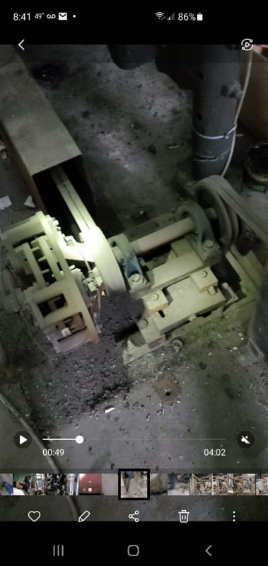
The primary rollers are driven by a 15hp size motor. The take-up roller is driven thru this same motor but there is an effective but Draconian clutch in between the motor and the take-up roller (thru loooong belts). It's simply a floating-on-the-end-of-a-spinning-shaft four caliper disk brake. As air is axially fed thru a rotating coupling the calipers are applied or not. The more air pressure the more the torque is passed thru.
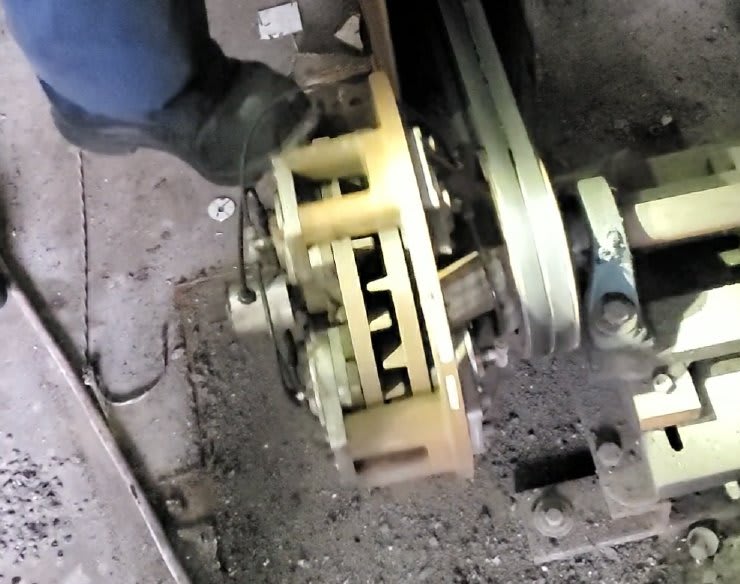
Laminator_clutch_1_oylslb.jpg


laminator_clutch2_jeiyo1.jpg


This seems a bit wasteful in that any operation while not locked up or completely unlocked is dumping heat electrically paid for. They also aren't fans of the long belt sets used. Further the belt-way causes some machine operational access annoyances.

I'd like to propose using two VFD motors instead. They have piles of motors laying around and offered "we already have whatever motor you want".

Questions:
1) Does converting this make sense to anyone besides me?

2) Since this clutch is a "torque" control device (with the limitation that the output speed can't happen to ever exceed the input speed) can one setup typical VFDs to be a torque drive without much concern about speed?

3) Can we get the same sort of operational functionality with two drive/motors that they're getting now with one motor, a clutch, and an air regulator, they constantly hand adjust all day?

4) If a two drive scheme seems plausible, any operational setup ideas would be greatly welcomed.


Keith Cress
kcress -
 
Replies continue below

Recommended for you

I suggest programming a torque limit on the drive.
I see two basic approaches.
1. Measure the diameter of the roll and adjust the torque to maintain a constant tension on the paper as the roll diameter increases.
2. Use a dancer roll to measure the paper tension directly.
A "Dancer" is a roll arranged so that it may be moved by the tension of the web.
The arrangement may vary from a straight sheet or web between two rolls with the dancer in the center causing a deflection in the passing web to an arrangement where the web makes a 180 degree wrap around the dancer and lifts it as the tension increases.
A signal from a dancer roll may be easier to use.
A diameter signal may have to be processed before use.
A consideration:
Once you get a dancer roll setup and outputting a 4-20 ma signal or similar, you can feed that to a PID controller and then to an E/P transducer (Electric to Pneumatic) and automate the existing setup.
You will same the cost of a VFD but still incur the friction losses.
Thanks for sharing your challenge with us, Keith.


Bill
--------------------
Ohm's law
Not just a good idea;
It's the LAW!
 
There are dozens of ways this system can be designed, and what you have now is one of them. Is it worth changing to another design. Probably not, unless there is a specific significant problem. This design lasted 70 years and will last another 100 years, with maintenance. That style of clutch is designed for sensitive torque control, and operators and maintenance people can easily understand how the system works by eyeball. Torque control of electric motors with gearboxes does not work well without torque sensors and feedback control.

Dancer arm sensing of tension along with motor speed control works well, but dancer arms have their own problems of getting in the way. Winders do not use constant tension during winding. That will result in telescoped rolls. Constant torque during winding is more desirable but will usually call for an operator to increase torque (air pressure to clutch) manually as the roll diameter increases to stay above a minimum tension. You can buy controllers that do this automatically.

There are a lot of things going on during winding and unwinding of rolls of materials. The properties of the material itself are among the most important.

Energy savings is highly unlikely justify the expense of changing. The ratio of the pulley is set to drive the winder fast enough so that it is faster than the feed rate to an empty core, so there is initially little slip or energy loss. As the roll diameter increases, slip at the clutch increases. The energy loss is easy to calculate.

If you want to learn more about web processing and products that serve that industry, subscribe to Paper, Film, and Foil Converter (PFFC) magazine .
 
The first thing you need to identify is what exactly is the requirement on the take up roller?

Is it really constant torque or constant paper tension or as compisitepro implies some god foresaken mixture of the two that in fact no one really knows or measures?

And thats then the second thing - how do you measure and control what will become a large mass of film (paper). Going from 4 inches in diameter to 5 feet is a huge change in the rotating mass.

I simply wouldn't mess with the system if it works other than maybe power the incoming belt with a motor located next to the clutch mechanism. Only if you can work out how exactly the operators decide how to adjust the clutch - i.e. what exactly do they consider during the day and how to measure what they are "feeling" or judging presumably with their eyes or maybe even sounds can you stand a change to automate the air pressure control on the clutch. Even then my guess is depsite the grumbles from the operators, after a few weeks someone will turn the control to manual and just adjust it themselves using a different dial...

Remember - More details = better answers
Also: If you get a response it's polite to respond to it.
 
Edit: dang it, I didn't read LittleInch's post and he seems to have the same thought.

My suggested direction would be to keep the clutch but add the VFD controlled motor. My logic is that the clutch has worked. The VFD driven motor can do 90% of the work and the clutch only needs to do a small fraction. This will reduce the wear and waste from the clutch while avoiding complete redesign of the system. One can operate the motor at a constant torque setting slightly below full requirement and let the clutch handle the rest.
 
But if you add the VFD, where does it run the system, why? If the VFD ever once doesn't result in enough torque then is it a failure? The existing is a brute force system that works, long history to prove that it works. All corner cases seem to have been covered. Will a radical redesign still cover all of those cover cases? Today, probably not. Sometime in 2023 or 2024 after long study and lots of data analysis, well maybe.

I’ll see your silver lining and raise you two black clouds. - Protection Operations
 
Doing the proposed change seems like a science experiment.
Center Driven Winders and Unwinders explains some of the complication. I think this can be done, and the mechanics are relatively simple. It is the controls part that is hard. It would require a drive motor /VFD system with a wide speed range sized for the low speed torque requirement (windup roll full).

This change could be worth while if the current approach is having enough down time or material loss related to failure to maintain appropriate product tension. Energy will not pay for this change.

Fred
 
What a bunch of stick-in-the-muds!

But, you're all probably correct. I was seeing it as an interesting 'experiment' with some customer benefits that I expect would work fine and would cost (materially) no more than the price of a measly 5HP VFD that comes down to turning two rollers the take-up reel sits on, like a dynamometer set of rollers.

I see the points made about the boundary conditions like where-in the take-up would stop completely if the one motor is stopped, with a separate drive you'd have to account for these types of events. There are web tightness issues that can screw up the product (laminations) if the take-up is too far off on its tension that they have a handle on now and would likely require learning they could do without.

I'll leave it as it is.

Thanks everyone for your sound council.

Keith Cress
kcress -
 
Is this correct for a center driven takeup:
Maximum diameter = maximum torque, maximum slip RPM and maximum losses.
Would it be difficult to monitor the speed of the driven shaft and command the motor speed just a few RPM higher? That may result in minimum slip RPM and minimum losses at all diameters.


Bill
--------------------
Ohm's law
Not just a good idea;
It's the LAW!
 
Status
Not open for further replies.

Part and Inventory Search

Sponsor