Continue to Site

Eng-Tips is the largest engineering community on the Internet

Intelligent Work Forums for Engineering Professionals

  • Congratulations KootK on being selected by the Eng-Tips community for having the most helpful posts in the forums last week. Way to Go!

Gearmotor rotation question

Status
Not open for further replies.

Logic11

Aerospace
Apr 25, 2020
9
This is probably a simple question to answer if this is your specialty but not my area of expertise. Got a 1/2hp early 80's Bodine 1 phase fractional hp parallel gearmotor and want to know if it can be wired to accept a reverse switch for the occasional use in reverse. The gear turns at 157rpm CW (11:1 ratio 1725 rpm motor). I do have a spec sheet that states under rotation CW. However in the bottom left it does sat under remarks: Wind per Dwg #12655
Connect for "CC" rotation
Could this mean that it can be wired for reverse as well?
 
Replies continue below

Recommended for you

Typically a single phase motor will state on the nameplate or wiring diagram if it is reversible. So if yours says that, it likely is. Even though “Clockwise” is an acceptable compound word making CC an abbreviation for Counter Clockwise, most of the time it is abbreviated CCW (for Counter Clock Wise) because it contrasts better with CW for Clock Wise when you want to show both directions on a diagram. “Forward and Reverse” are totally subjective terms. So from what you describe, it appears as though your motor is reversible.

Did you try contacting Bodine for a copy of that wiring diagram?


" We are all here on earth to help others; what on earth the others are here for I don't know." -- W. H. Auden
 
Yes, contacted Bodine but they didn't have a wiring schematic because of its age? Any way to know if it is in fact reversible? I would have thought "CCW" or "Reversible" would have been the likely addition under remarks but not exactly sure what "CC" means? Any way to tell?
 
Is this a worm drive gearbox?
Does it have thrust washers for both directions?

Bill
--------------------
"Why not the best?"
Jimmy Carter
 
That I dont know. I thought most of the side shafts are worm gears but not sure on this one. I suspect its splined gears that mesh together? But not sure really. If thats the right term?
 
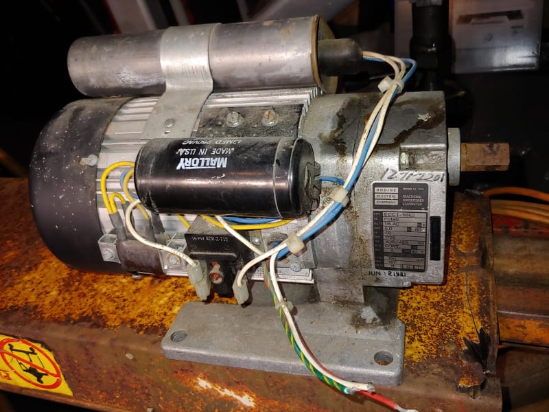
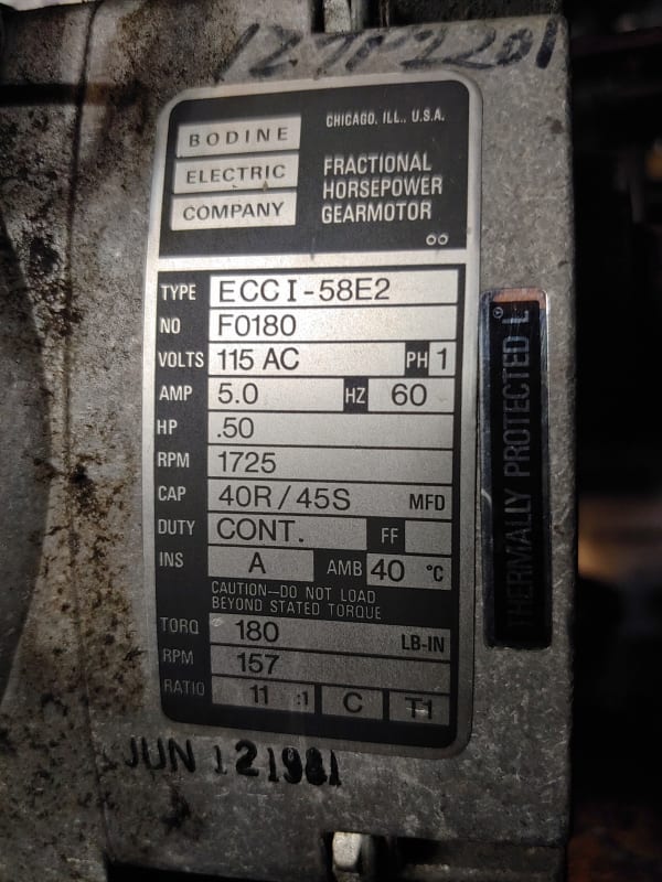
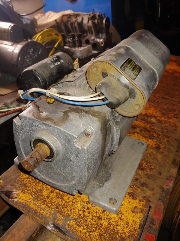
Here are pictures of the motor and tag

20200425_203758_HDR_vihric.jpg


20200425_203839_HDR_cppxkf.jpg


20200425_203854_djjgha.jpg
 
There have been some threads just recently about changing the direction of single phase motors. Worse case, it seems, you have to dive deep into the windings to get at some of the motor connections. I assume those connections could be brought out and wired to a multiple pole switch to give to a reversible motor.

Your inline gearbox is probably a planetary or helical gear drive - both reverse just fine.
 
Please accept that electrical isn't my strong point( why aerospace piggybacked my username I have no idea? Big fingers?) but couldn't I simply add a reversable switch like the ones sold at Harbor Freight or Princess auto Brian?
 
It may be simpler. That drawing #12655 might show that all the leads have been brought out. Can you sketch out which wires go where? I'm guessing the electrical guys here could take that and run with it.
 
Hey Brian, is there a type of gear that could be in there that isn't reversible?
 
Hi Logic11. You can correct your industry under the blue tab at the top right, "My Stuff/MyProfile". The choices were in one of the pulldown boxes when you first registered, the box must have slipped on you while you were filling the page out.

For your spec sheet its note of CW rotation is presumably the output shaft. The "connect for CC rotation" note may be for the motor itself with the difference being because of the number of rotation changes in the gear box.

For your wiring question:
-the nameplate gives the capacitor sizes as 40 mfd run / 45 mfd start so that will distinguish the 2 cans on the housing (okay, the black one says 43mfd)
-the brown lozenges at the lower left with yellow wires look like resistors, unusual and so would make me more hesitant about guessing the reversing connections
-the black cube with the red button is probably the centrifugal switch (well, funny location). 3 connections instead of 2 make it look suspicious too
-by the labelling there is a thermal protector, another connection point to account for. I don't see it on the outside so we might have to look inside to complete our understanding of the wiring
-the only clear wiring is the cut supply wires of red=hot, white=return and green/yellow=ground

As a design family this motor is very likely reversible but I see enough complication that I would be hesitant without the maker's info. I can trace many of the wires in your photo but not enough. This PDF suggests that swapping the main winding leads would reverse it but I can't see enough of your wiring to tell, especially inside the case. Even then if this has been custom built for one direction it may not have equal performance in reverse even if it can be reversed.

For the gear question:
-worm gears involve a lot of thrust so the availability of bearings on both sides is important for a reversing application (waross's point)
-helical gears involve a small amount of thrust, there is a good chance that thrust washers exist on both sides as matter of this motor family being designed for many configurations
-spur gears don't have a side thrust but as slopping about against a soft casing is not a good idea there is a good chance of simple washers being in place.
As mentioned yours is not a worm drive but you would have to take the box apart if you felt you had to be sure about the washers for the other gear types.

As this is getting bogged down are we just dealing with curiosity or would the motor be useful if it could be reversed?

Bill
 
I don't know of a gear drive that can't be run in both directions. Worm gears with a low enough lead angle can't be back-driven (gear rotates worm) but they can still drive (worm rotates gear) in both directions.
 
Not curiousity at all, complete funtion needed here. I'm installing this on a modified bead roller for metal shaping and auto body forming. The amount of reverse direction will be very minimum. I plan to add an extra gear shaft to bring the rpm's down to a crawl which is necessary for what I need to do. Right now I need an extra set of hands sometimes so with a foot pedal and a gear reduced motor I can accomplish shaping on my own.
 
In manufacturing every penny counts.
A generic worm drive would be expected to have thrust bearings for each rotation.
A purpose built motor for a particular application that never reverses may be configured for one direction only.
An unknown thing with wires? I'll guess a thermal protector.
An unknown thing with three wires? I'll guess a starting rely rather than a centrifugal switch.
Or something else.

Bill
--------------------
"Why not the best?"
Jimmy Carter
 
Bodine is happy to help you. (Or maybe not)
Bodine


Bill
--------------------
"Why not the best?"
Jimmy Carter
 
Actually Bodine was trying to help and looked into whatever information they had but were unable to give me a definitive answer. They went out of their way as far as I'm concerned and didn't simply sluff me off. Also gave me another contact who hasn't responded so not sure if this crisis has left them in a bind like so many others.
Honestly, I appreciate the information so far from everyone here but never meant any of this to spark a debate or test anyone's knowledge. You could tell me that any of the items attached to this motor are hair driers and I'd be inclined to believe you. Again, besides having a general understanding of basic electrical/electronics (not my strong point) and my interest is in making panels from thin metal sheets and welding them to an automobile. Old school stuff that seems to be a dying art. I'm hoping this tool will help me accomplish that. Maybe I'm missing something and again do appreciate all information given but won't trouble you guys any longer. I'll just add a large handwheel to an additional shaft and extra gear for the odd time I need to move a panel in reverse. Was just looking for an easier method so though why not think outside the box and ask from experience.
Thanks everyone for your time
 
Looks like a standard Bodine PSC motor with an external capacitor. I have used Bodines for years on little projects, the wiring has not changed ever. Here is a current Technical Paper for one, it shows the same wire colors that you have.


" We are all here on earth to help others; what on earth the others are here for I don't know." -- W. H. Auden
 
Status
Not open for further replies.

Part and Inventory Search

Sponsor