Continue to Site

Eng-Tips is the largest engineering community on the Internet

Intelligent Work Forums for Engineering Professionals

  • Congratulations waross on being selected by the Eng-Tips community for having the most helpful posts in the forums last week. Way to Go!

General Profile Tolerance Interpretation

edw.jack23

Industrial
Jun 22, 2022
9
Hi all,
I have a part with a general profile tolerance that apply to linear basic dimensions such as in the figure below. The question I'm having trouble with is how much "tolerance" the linear dimensions have. Take the 60mm dimension for example it seems that one side can vary .4 and the other .8 so is there a tolerance of ±.12mm? Or is it entirely surface based and there is not "total". Let me know if I need to clarify. Any help appreciated!


1738342825352.png
 
Replies continue below

Recommended for you

The linear dimensions have no tolerance. The tolerance is how much the part is allowed to vary from the basic dimensions.

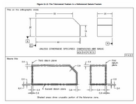
There is something seriously wrong with the "shaded areas" of that diagram.

The underlying concept is that the variation is from the true profile and the true profile in this example originates where contact with the datum feature simulators would be. The outward variation allowed by the profile of surface geometric characteristic from the surface would be embedded in the datum feature simulator (like sitting on a granite plate). Since it clearly cannot be embedded, any portion of the part variation that would be embedded into the datum feature simulator is discarded.

All the variation volume on the opposite side of these datums is unusable, but gaps along the datum features with the datum feature simulators can still have their half of the tolerance zone.

You can shave 0.04 on a portion of the surface in contact with the datum feature; there will always be 0.00 contact vs. +/- 0.04 on the opposing side.

If this was a lumpy block of wood and you wanted to just touch the opposite surface on the [60] dimension that would (pun!) be 60.04. The maximum you could remove and be in compliance would leave 59.96. If you wanted to measure the shortest distance where the contact with the datum feature simulator had a notch or hollow, that would be 59.92.
 
The tolerance zone is 0.8 mm wide everywhere, but at the datum features only half of it available. If you want to know Min and Max distance between opposed points on the left and right surfaces that would be 60.4 Max and 59.2 Min. If you are looking for the Min and Max distance of the right face from datum plane B that would be between 59.6 to 60.4.
 
I would not challenge Fig 11-21.
Why not? The shaded portion is clearly labeled as unusable portion of the tolerance zone while the shaded portion is clearly the entire given tolerance zone.

Is there some reason to think that this is OK?
 
I'd be interested in knowing the source of the diagram. It's not ASME Y14.5, is it? I think all of the variation needs to be considered to be opposite of (or away from) the datum surfaces, since it is the datum surfaces from which you are measuring. I think that the part would be better designed with flatness controls applied to the datum surfaces.
 
I'd be interested in knowing the source of the diagram. It's not ASME Y14.5, is it? I think all of the variation needs to be considered to be opposite of (or away from) the datum surfaces, since it is the datum surfaces from which you are measuring. I think that the part would be better designed with flatness controls applied to the datum surfaces.
It's ASME Y14.5-2018.
 
Hmmm... I'm not going to dispute a released version of ASME Y14.5. If I were the Designer, I would avoid the question by applying flatness controls to the datums to limit the variation and ambiguity there.
 
Hmmm... I'm not going to dispute a released version of ASME Y14.5. If I were the Designer, I would avoid the question by applying flatness controls to the datums to limit the variation and ambiguity there.

This is the standard's explanation:

"
11.4.3 Profile on Nonsize Datum Features
When the toleranced feature is or includes the refer-
enced datum feature, the profile tolerance is affected
as described in paras. 11.4.3.1 and 11.4.3.2.
11.4.3.1 When the Toleranced Feature Is a Nonsize
Datum Feature. At the datum feature, the distance to
the true profile is zero. Since the datum feature may
not pass through the datum plane, the tolerance on the
considered feature shall be as follows:
(a) For an equal bilateral profile tolerance, half of the
profile tolerance is available for variation of the datum
feature. See Figure 11-21.
(b) For a unilateral profile tolerance, the tolerance may
only be applied into the material of the feature. "
 
This figure is a known typo. Of course the ENTIRE tolerance zone can't be unusable. This is a frustrating thing. It's not the only figure in error either.
 
With that in mind, let me go to the ASME site and find the errata sheets for that standard.

Just joking.

There are not any there because they don't take responsibility for their errors.

Here's a question, is the printed version different from the DRM PDF version? That is, if you purchase successive copies of the DRM PDF version, are they putting in corrections for the later digital copies?

Hey, ASME, there is a low-effort way to shake cash from industry. Release a new, typo correct version every few months for full retail price. Don't fix them all at once and don't offer any update unless the buyer has purchased the previous one.
 
Is this from now on another thread to complain about ASME, and how greedy and wrong they are?
 

Part and Inventory Search

Sponsor