Eng-Tips is the largest engineering community on the Internet

Intelligent Work Forums for Engineering Professionals

  • Congratulations waross on being selected by the Tek-Tips community for having the most helpful posts in the forums last week. Way to Go!

Generator Calculations Bug 3

Status
Not open for further replies.

gvasiliou

Electrical
Mar 24, 2012
41
0
0
GR
Hi guys,
For one more time I need your opinion in a kind of strange issue, which escapes my understanding.

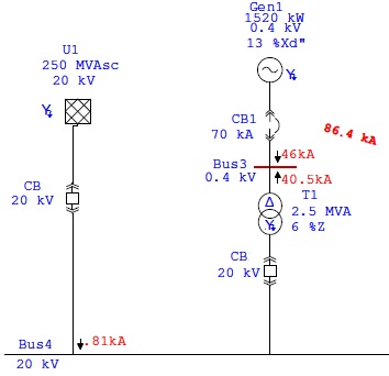
Performing a single line to ground short circuit calculations (Low Voltage Side) in a simple Generator power plant using a step up to transformer, we can observe the two following facts:

1. For a stand alone generator (not parallel to the grid) single line to ground fault current (low voltage side) equals to 30kA. This value actually represents that behavior of the generator itself.

Gen+Only.jpg


2. If generator works in parallel to the existed grid, results of the short circuit fault current calculation equals to 86,4kA. This total fault current splits to 46kA coming from Generator side, 40,5 kA come from grid side.

Gen+Grid.jpg


The question is:
Since generator as a source is capable to provide 30kA on it’s own, how is it possible in a parallel to grid configuration to have 46 kA coming from the generator? It seems 16 kA have been added to the generator side. Is this fault current actually going thru generator windings?

PS1 : Please notice that the above results in both cases can be reached either by a simulation software or by hand calculations using symmetrical components analysis.

PS 2: Quick Description of equipment:
Generator is 1,9MVA , cosF 0,8, 400Volts, 50Hz, Star connected, solid grounding, Xd’’ = 0,13 p.u.
Step Up Transformer is 2,5 MVA, 6% impedance, Delta connection at LV Side, Star Connection (solid grounding) at 20kV Side. Grid is 20 kV , 250MVAsc, star – solid ground.
 
Replies continue below

Recommended for you

A common, but not well enough known, phenomena.

Draw out the sequence network. For utility only, you have the utility impedances in series. For generator only, you have the generator impedances in series. Using some generalities, we can say that the utility has a medium (+) and (-) impedance and a high (0) impedance while the generator has a high (+) impedance, a low (-) impedance and a very low (0) impedance. When paralleled, the resulting impedance is always lower than the lower of the impedances.

When separate, the utility contribution is limited by the (0) impedance, but the generator contribution is limited by the (+) impedance. When paralleled, the utility (0) is essentially shorted out by the much lower generator (0).
 
Hi david,
Actually in my configuration the utility (0) can't reach the fault location due to the existance of delta winding on LV side of the intermediate transformer. As a result, if you try to draw utility only fault circuit (i skipped this from my post) the fault current at LV bus 3 will be zero, since utility zero sequence impedance doesn't exist thus the calculation result is zero ( i have already perform this calculation).

I can agree with phenomena you describe as a commons general rule. When a unique source works alone impedances are added in series (pos, neg, zero).
When sources works in parallel, especially for single line to ground fault, impedances of each source is in parallel (parallel and smaller pos, neg and zero) resulting in a smaller impedance in general.

What really i would like to know if this extra 16kA that comes out from the reactances combination (in parallel to the grid configuration) is a real current going through my generator windings....

Thanks in advance.
 
Possibly the utility infeed is large enough to prevent the generator terminal voltage collapsing fully, thus providing the AVR with a source of power to boost the field and maintain output. Normally the output of a machine equipped with a bus-fed exciter will collapse if a solid fault occurs close to the main terminals. Depends on what type of AVR you have, also how good your model is. A PMG-based AVR will fare better than a bus-fed type when faced with a close-in fault.


----------------------------------
image.php

If we learn from our mistakes I'm getting a great education!
 
I agree that an ungrounded delta winding will not contribute to a ground fault, but I believe that the connection to the grid will boost the fault current.
Consider the well known action of induction and synchronous motors when the voltage on one phase starts to drop. Current will be transferred through the rotor from the healthy phases to the dropping phase to maintain the voltage. This current will be limited by the impedance of the source as well as the impedance of the motor with the motor impedance predominating. As the voltage drops to zero (solid fault) the current increases to fault levels.
The current path is through two windings in parallel in series with the third winding. While zero sequence impedance is often 3 x Z, in this case the series parallel path will result in an impedance of 1.5 x Z That would account for the current being 50% higher when connected to the grid.
Comments??

Bill
--------------------
"Why not the best?"
Jimmy Carter
 
Waross, for sure grid boosts the fault current using positive and negative sequence contribution , even if zero sequence of the grid is not able to reach the fault location due to the transformer delta.
I can even understand the path you describe, if i draw the impedances using symmetrical componentns analysis it looks like this:
Pos Sequence : [Zgen] in parallel to [Zgrid]+[Zt/f]
Neg Sequence : [zgen] in parallel to [Zgrid]+[Zt/f]
Zero Sequence : [Zgen] only.

At the end , total impedance is [Zpos] + [Zneg] + [Zzero], and total current is Ik'' = 3 * (E/Ztotal)

If now you split the total fault current trying to find out what is the generator contribution to this fault under these circumstances, then you reach to the result of 46kA , actually 50% more of the generator contribution in stand alone operation.

But still is not clear to me:
Increased current is due to the grid contribution.
is this 50% more current really going thru my generator windings, meaning that for some time, generator windings are exposed to 50% more fault current from what these windings actually can supply and withstand?

PS : You can see the detailed calculation in the attachment

 
 http://files.engineering.com/getfile.aspx?folder=0d7a00a8-97b3-4dd4-946f-84fdd2422de5&file=Leg_Calculations_Corrected.pdf
Yes, the increase is due to the reduction in (+) and (-) impedance caused by the presence of the utility system. Current through the generator winding for the faulted phase is the sum of the sequence currents through the generator. If your math is correct, yep, you have 45.4kA from the generator. Maybe time to consider impedance grounding the generator.
 
LOL....
That sounded something like :
Apply some impedance to your machine and stop posting questions! (just joking).

I'm afraid math is correct. Calculations have been checked even by ETAP.

Before to put my hand to my pocket to draw a lot of my company's money for applying neutral impedances to all generators, in this late stage of a (finished) installation, i will try to insist more with Stamford Engineers.

If this 50% extra fault current is really going thru my generator windings, maybe this Generator is capable to handle the total current of almost 46kA for some milliseconds ... until the installed Short Circuit protections (i.e LV C.Breaker trip unit, independent CTs on generator terminals, Earth CT fitted on the generator neutral, etc) to operate and isolate the fault.
 
One more explanation:

When the grid is not connected, the currents in the HV-windings of the transformer are zero. And because of that, the currents in the LV-windings are also zero. This means that current can flow to the earth only from the faulted phase, because the currents in the other phases must go through the LV-windings to reach earth.

But when the grid is connected, the currents in the HV-windings can be nonzero. This means that the currents in the LV-windings can also be nonzero, and the currents in the unfaulted phases can flow to earth.
 
The faulted phase winding of the generator is supplying part of the fault current and the grid contribution is also flowing in the faulted phase winding. That generator winding will see all of the current fault. The unfaulted phase windings of the generator will carry the grid contribution of the current only.


Bill
--------------------
"Why not the best?"
Jimmy Carter
 
The unfaulted phase windings of the generator will carry the grid contribution of the current only.

Can you explain this a little bit more...I was expecting unfaulted phase windings of the generator to contribute to the faulted phase by a small fault current (calculated using the a operator). I wasn't expect unfaulted windings to carry grid contribution....
 
The unfaulted windings are the path from the grid through the rotor to the faulted winding.


Bill
--------------------
"Why not the best?"
Jimmy Carter
 
OK... If it is like that, this explains why the fault current coming from the generator side is 50% increased versus standalone operation. As well this proves that generator windings are in reality exposed to higher currents from what they can really produce (and most probably withstand).

I manage to get today a quote for an LV resistor to examine the possibility of modifying the existed system. I was pleased enough to see that cost is low for a LV resistor (something like 100 euro).

But now i have other kind of questions...like:

It is preferable to have low resistor grounding (i.e providing 200Amps) or high resistor grounding (i.e providing 10Amps)?

Is the normal operation of the alternator going to be affected...?

Should i start a new thread...?
 
Once you go for impedance grounding you may as well go high (lower current) to limit possible damage.

Bill
--------------------
"Why not the best?"
Jimmy Carter
 
After some initial research:
High impedance earthing (low current i.e 10A) needs special treatment by protection devices to ensure correct "understanding" of the fault current.
For this reason some times low impedance (high current i.e 200Amps) is used, since higher currents can be picked up by protection devices more easily.
Moreover in case of high impedance grounding - low current like 10Amps there is a possibility to have fake pick ups due to loads unbalance in normal operation (10Amps asymmetry in LV Generator is not so rare in a power plant).

Furthermore , high impedance looks like "ungrounded" system, and there is a possibility over-voltages to appear in case of faults (or other voltage related phenomenon).

I'll keep researching. In case you have more experience with impedance grounding and you can help, you are welcome :)

 
Status
Not open for further replies.
Back
Top