Continue to Site

Eng-Tips is the largest engineering community on the Internet

Intelligent Work Forums for Engineering Professionals

  • Congratulations GregLocock on being selected by the Eng-Tips community for having the most helpful posts in the forums last week. Way to Go!

Generator Reconfigure 1

Gen15

Electrical
Oct 30, 2024
14
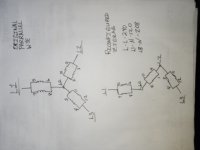
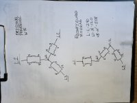
I am working on an older Generac generator for a customer who is going to use this unit in a different application. The voltage is 208/120 parallel wye. I am going to change it to 240/120 double delta. The gen is a 1998 trailer unit and I have not found any resources on a reconfiguration for this gen end. The windings are not labeled NEMA standard. I have tried mec alte drawings because they were numbered the same as mine but I had to shut it down as soon as it excited because the engine loaded up. I've tried Generac's achieves but with no success. Any help in identifying my windings would really be a help. I have attached a data plate for the gen and a crude drawing of my original configuration. The 12 leads were numbered as they appear on the drawing. My model number is 98A03931-S. My serial number is 2042813. My windings are 1-2, 3-4, 5-6, 7-8, 9-10, 11-12. This is far from Generac's normal of 1-4, 2-5, 3-6, 7-10...... Any help would be appreciated.
 
Replies continue below

Recommended for you

Why not use Zig-Zag? (Edit)
One connection change and a continuity check.
No need for wire numbers.
This is a recognized three phase to single phase connection.

Label your wire pairs L1, L2, and L3.
Your numbers don't have to correspond to existing numbers.
If you picked L2, Use a continuity tester to find the corresponding neutral end of the L2 winding and label it L2n.
Connect L2n to L3 and insulate and forget it.
You will now have 120/240 Volts single phase between L1, N and L2.
You don't have to use L2.
If you identify any neutral end of a winding and connect it to either of the other two line leads and then insulate the connection, you will have 120/240 Volts single phase between the remaining two leads and neutral.
So much quicker, easier and safer than double delta.
This was once the standard single phase connection shown on older sets for single phase use.
 
Last edited:
Thanks for the connection instruction. My drawing and data plate was too much data to attach. So I wrote my winding numbers along with the model and serial at the bottom of the page. When you say double wye you are talking about what I call parallel wye. So starting with that I change a few connections and can produce 240 L-L
120 L1-N and 120 L2 to N. Is this right? I am drawing out your instructions right now.
 
In this their any disadvantage or loss to this configuration? Is it more or less efficient than a double delta? Is your recommended connection considered a zigzag configuration?
 
My original connection was:
L1- 7,5
L2-1,9
L3- 4,12
N- 3,8,6,10,2,11

Again though this looks off my windings are:
1,2
3,4
5,6
7,8
9,10
11,12
I chose L3 because of my wire routing. I took 3,11 and connected to 1,9 which was L2. I got 240 L-L. L1-N- 120. L2-N was 208. Was my choice of connection the problem. Should I have taken 3,11 to 7,5? This is my first restrap without an available diagram. I'm learning. I hope.
 
I mis-spoke.
I said "Double Wye" when I meant to say "Zig-Zag" connection.
So easy.
Just disconnect one phase neutral leads.
Do a continuity check and connect the leads to either of the other phase lines and tape up.
Connecting the neutral of one phase to either of the other two phase lines will give 120/240 Volt single phase, with no phase angle shift between the 120 Volt windings.

There is a related connection called the "Collin's connection" or Bar-Diamond connection, that will give the same result with ten lead generators. (Delco once made a lot of ten lead machines. They were commonly found in Telco take-outs. One wye point connection was buried with one lead only brought out.
Eg: leads 10, 11, and 12 were connected internally and only lead 10 was brought out.

The zig-zag has been ued by major gen-set manufacturers.
Voltage drops and losses are the same.
Both double delta and zig-zag reduce the KVA capacity by 1/3.
The kW capacity is dependant on the prime mover and will increase to the KVA capacity.
EG: PF 0.8 or 80% becomes PF 1.0 or 100%.
Actually, The set will be overpowered and available input kW will be 120% of allowable KVA.
(power factor of 1.2, but not to imply over-unity??)
 
Forget the numbers.
Just disconnect one set of neutral leads, check continuity and reconnect to a different phase line.
You will have used one of six possible connections.
It just doesn't matter.
All six possible connections give the same 120/240 Volts.
 
I have moved the neutrals to another phase but my result is 120 L-N and 208 L-N. 240 L-L. Before this I used 2 other zigzag configurations with the same results. The 208 is always the result. ???
 
Are you sure you are metering properly? Looks to me like you may be metering from the middle of the zig-zag.
 
Last edited:
I attached a pic of yesterday's change. Sorry but I had to greatly reduce the quality so it would attach.
 

Attachments

  • IMG_20241031_080830.jpg
    IMG_20241031_080830.jpg
    108 KB · Views: 5
I attached a pic of yesterday's change. Sorry but I had to greatly reduce the quality so it would attach.
Sorry for the image size limitation. I have increased the allowable file size so please re-attach the higher quality image if required.
 
Here is a better pic.
 

Attachments

  • IMG_20241031_091926.jpg
    IMG_20241031_091926.jpg
    6.5 MB · Views: 6
Is it possible that the last pair of windings should be flipped?
 
Your connection is correct.
The point that you are using as the neutral and the point from which you are reading 208 Volts---
TAPE IT UP AND FORGET IT.
The original neutral is still the neutral, not the leads that were removed.
 
Last edited:
My neutral connection for my load should still be 8,6,2,10 right? Tape up 9,1,3,11 right? That's what I have L3-N is 208. L1-N is 120. If I measure from mt tie up point (1,9,3,11) it just moves my 208 to L1-N. Am I still not understanding?
 
PROBLEM SOLVED!! I prayed and flipped the last group over. L1-N 120, L2-N 120, L1-L2 240. The orientation of the windings came from interposing nema numbers over my only " "known good" configuration. I guess there was still a bit of difference is why I got the odd voltage. I strapped it DD as well and it worked as well with the windings turned over. Thanks for all the help!
 
After a 2 hour load bank test, my load was balanced and my voltage was stable throughout the test. My windings were almost ambient tempature at 80% load. I started out not knowing the start and stop wires on each winding. I had no way to see that with the equipment I have. I have probably restrapped a hundred generators over the last 13 years and have never seen a gen numbered like this, or configured like this. It's generally as easy as the alphabet. When I flipped 3-4 and 11-12 it worked. Thank the Lord! Thanks for all of your input. It's good to have access to knowledgeable people.
 
Your connection was correct.
You taped up the wrong connection.
 
No sir. The 4 neutral leads landed on an isolated neutral bar in the electrical cabinet. The four leads that were isolated were tied up wrapped in splice tape, abrasive wrap, and covered with super 88. The voltage was still 208 L1-N and 120 L2-N. If you look at the picture I attached on 10/31 you can see the joint marked L2. This is what I isolated (3,11,1,9). But the voltage was still off. But because I had no knowledge of the windings I was not confident that every winding was connected to the proper end of the winding. After some sketching and praying I flipped 3-4, and 11-12 over. This put 4 and 12 to the isolated joint and 3,11 to my breaker. And now the line to neutrals are right.
 

Part and Inventory Search

Sponsor