Continue to Site

Eng-Tips is the largest engineering community on the Internet

Intelligent Work Forums for Engineering Professionals

  • Congratulations KootK on being selected by the Eng-Tips community for having the most helpful posts in the forums last week. Way to Go!

Generic radius of curve for cargo securing calculations 1

Status
Not open for further replies.

TrustButVerify

Mechanical
Sep 27, 2023
48
Hello,

I'm trying to set up a spreadsheet to calculate the cargo securing or lashing needed to secure a load to trailers in order to make the transportation safe for a lot amount of kilometers.

A force I need to calculation is the centripetal force acting on the convoy while doing a curve, and one of the input is the radius of the curve.

The thing is I'm doubtful over is there is a minimum radius often considered for road design, in order to avoid to go through a route survey of the specific road to take study each one of the curves.

Thanks in advanced, and have a nice week.
 
Replies continue below

Recommended for you

If centripetal force exceeds the tipping point the lashing does not matter anymore. The cost of using the truck tipping point for lashing design, vs something less should be much smaller the the cost risk of tipping due to load shifting.

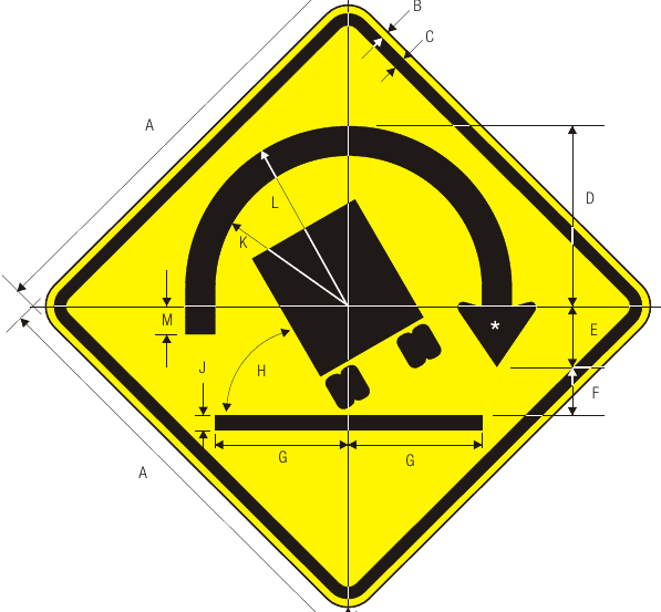
Do your drivers ignore these signs?
Screenshot_from_2023-11-17_17-39-45_mqifxp.png
 
i never see this sign in my country. i dont know how iportant this sign calculation. to avoid an accident like this to our truck, usualy we use proper super elevation design and we put sign limit speed.
 
The following may be of interest:

(3) For subsection (1), the circumstances are that the loaded
vehicle is subjected to:
(a) any of the following, separately:
(i) 0.8 g deceleration in a forward direction;
(ii) 0.5 g deceleration in a rearward direction;
(iii) 0.5 g acceleration in a lateral direction; and
(b) if friction or limited vertical displacement is relied on to
comply with (a), 0.2 g acceleration in a vertical direction
relative to the load.

Ex:

Load Restraint Guide

 
In answer to harfen
The tipping truck sign is used in the US to supplement reduced speed limit signs on turns. They are often seen on cloverleaf interchange ramps which have super elevation. High center of gravity creates a tipping risk that can not be mitigated by tiedowns.

Use of signs like this is dependent on local law. In the US case Manual of uniform traffic control Devices, Section 2C.11 Truck Rollover Sign (W1-13)
 
Some of those acceleration values seem a bit too high. Perhaps you have included some factor of safety, but I doubt there has ever been a commercial tractor that could generate forward (or backward) accelerations on the order of 0.8g. A realistic limit for the forward deceleration for a loaded commercial tractor with a loaded semi-trailer (air brakes) is about .6g if it is in really good shape and depending upon where its load is positioned. But on average, you can expect somewhere around .3g to .4g for a loaded rig in full lockup condition. Positive acceleration is much much lower than .3g.

As for the OP's question, there are analyses that range from very simple to incredibly complex for what you are asking. The basis for most of them is the equilibrium between the cornering force caused by the turned front wheels and the pavement friction. If there is sufficient friction for the truck to maintain a curved path, then the question becomes how does the load behave in consideration of Newton's first and second laws? A very simple analysis will only consider the radius, the speed of the truck, and the friction of its tires on pavement. In this case, the radius of the curve at the point in time that the tuck tires lose traction is based upon the relationship r = V^2 / (mu x g). You can then convert velocity to energy or momentum or whatever. Obviously, you are interested in some radius that is larger than this because before the tires lose traction the truck/trailer will usually start to roll if not on a slippery surface. This makes it a lot more complicated, and the height of the load, the stiffness of the suspension and the design of the king-pin all enter into the analysis. The fact that the truck is articulated is a real problem, but it can be dealt with in a very general sense. I would suggest that you draw a free-body diagram of the truck at the moment of tipping (kind of like the sign shown above) to get an idea of the forces involved.

Also consider that the majority of rollover formulas that have been published are based upon static forces in equilibrium at the moment of tipping and not a rigorous evaluation of the vector dynamics or a finite element analysis. They are also mostly concerned with single-unit vehicles, because as I said, it gets very complicated once you have a loaded trailer involved. If you really want to research good mathematical treatments of the subject, A good source for research papers on the subject is the Society of Automotive Engineers (SAE). Research papers aren't free, but they aren't prohibitively expensive even for non-members. Also take a look at the TRID database. It's a free database of transportation research conducted by just about every source imaginable. You can't get the research papers at TRID, but you can get the citations and usually a link to where they are sold.

 
Status
Not open for further replies.

Part and Inventory Search

Sponsor