Continue to Site

Eng-Tips is the largest engineering community on the Internet

Intelligent Work Forums for Engineering Professionals

  • Congratulations KootK on being selected by the Eng-Tips community for having the most helpful posts in the forums last week. Way to Go!

Get forces and moments from connection using APDL

Status
Not open for further replies.

dixib

Mechanical
Dec 1, 2011
21
Hi

Is it possible to extract force and moment reactions from contacts using APDL?
First I need to say that I'm new to APDL, and only have basic knowledge of other programming languages. Here's a more descriptive explanation of what I'm trying to achieve and what I've done so far (no final script, so have not tried to run anything).

We have models with bolts that are split and have bonded connections at desired cross sections. Normally we insert force and moment reaction probes for each connection, then make a plot and copy paste from this to Excel to process the data further. If possible we'd like to get these values using a command block to minimize the setup work and hopefully minimize the risk of possible errors in the extraction.

So far I've added a command block at each connection to get a meaningful definition to identify them. The code follows the following definition:
Code:
BB_1_1 = _cid

The definition is made up of three parts:
[ul]
[li]BB which indicates that it's a Bottom Bolt[/li]
[li]The first 1 is the bolt number[/li]
[li]The last 1 is the cross section number for that bolt[/li]
[/ul]

Using this definition I intend to make nested loops (*DO) to extract the values in the desired order.

In the extraction command block (placed under solution) I define some parameter:
Code:
Prefix = 'BB_'					! Prefix used before numbers in command block @ connections
NoB = 3						! Number of bolts
NoS = 3						! Number of sections pr. bolt
ExtS = 3					! Time at which to do first extraction
ExtF = 6					! Time at which to do last extraction
Increment = 1					! Time increment between extraction points (will usually be 1)

! NAMING OF EXTRACTED LOAD CASES		! Named based on ExtS, Increment and ExtF with prefix LC.
						! If ExtS = 3, Increment = 1 and ExtS = 6, then naming should
LC3 = 'Load case 1'				! be LC3 = '', LC4 = '' ... LC6 = '' (name of load case
LC4 = 'Load case 2'				! between '').
LC5 = 'Load case 3'
LC6 = 'Load case 4'

The I start to make the loops:
Code:
*DO,i,ExtS,ExtF,Increment			! Loop for load cases
 SET,NEAR, , , ,i, , ,				! Sets the load step to read data from
 LCNo = chrval(i)				! Current load step as character
 LC = strcat('LC',LCNo)				! Current load case name

 *DO,j,1,NoB					! Loop for each bolt
  BNo = chrval(j)				! Current bolt number as character
  BNoP = strcat(Prefix,BNo)			! Creates prefix for each individual bolt

   *DO,k,1,NoS					! Loop for each section of current bolt
    SNo = chrval(k)				! Bolt section as character
    BS = strcat(BNoP,'_',SNo)			! Full bolt and section definition

    *GET,Fx,BS					! Get value from connection

This is how far I've come so far. I don't know if this is the best way to make the extraction?
I haven't been able thought to find out how to get the values from the contacts using the *GET command. Reading through the manual hasn't helped me getting the answer.

Finally I'll of course also need a file creation (*CFOPEN) and write command (*VWRITE) to make the file to import the results in Excel, but I'm not quite there yet. I was guessing that I could make the script without and make a readout in the results of the command block to see, if I was getting the right results, before adding more to the script. Still need to figure out how to extract the reactions from the contacts though. Hoping someone can help with this. Preferably with a good explanation, as I'm having a hard time getting to know APDL, as I don't find it very intuitive.

I've got the book: Introduction to the ANSYS Parametric Design Language (APDL) but haven't found it too helpful in learning the language. Are there any good tutorials around for a beginner to start learning APDL?

Thanks in advance!
 
Replies continue below

Recommended for you

Hi dixib,

Instead of [tt]BB_1_1 = _cid[/tt], use [tt]BB_1_1 = cid[/tt] in your contact command snippets.

Your idea for your macro is forming nicely. In your /POST1 command snippet, use these commands:
[tt]FSUM
SPOINT
*GET, my_fx, fsum, 0, item, fx [/tt]for force extraction.

A critical point to read up in FSUM is "the nodal force and moment contributions of the selected elements attached to the node set".


Kind regards,
Jason
 
Hi Jason

Thanks for your guidance. I've had some time to look at things further, but am still having some trouble.

The underscore before cid was taken from a script that someone else have made, that does something similar to what I want. I haven't been able to find out if it makes a difference though, as I haven't been able to select the contact elements for further processing. I've found this site (Link) that tells about the APDL script equivalent to a contact reaction probe. Using ESEL to select the contact elements doesn't seem to work though. Everything seems to be working up to and including the last *DO statement, with a little adjustment, as it's apparently only possible to concatenate two strings with the STRCAT command. Hence, I've changed the last parameter definition to:
Code:
BS = strcat(BNoP,'_')
BS = strcat(BS,SNo)
Is it possible to concatenate more than two strings in one command?

After this I've entered:
Code:
ESEL,S,TYPE,,%BS%

This just produces a warning saying: Specified range of 0 to 0 is not permitted. The ESEL command is ignored..
It seems to me like, the BS definition doesn't produce the right link to the definition made in the command blocks at the contacts. BS is correctly defined as equals BS_j_i. Looking through the Post Output I can't seem to find the BS parameter being redefined for each loop. Is some extra code needed for this to happen? The loops otherwise seem to work and values seem to be found for each "bolt section". Same values are found for each loop, as the ESEL command doesn't work.

To match moment reaction probes, I need to find the centroid as the summation point. I'm not sure how this is done. I found a reference to KSUM, but this is a pre-processing command, and doesn't work in my case. Unless I have to find the centroid coordinates in the command blocks at the connections. I've tried using ETABLE, but can't verify if this is a viable option, as the ESEL command doesn't select the desired elements. The commands if used so far are:
Code:
ETABLE,Cx,CENT,X,AVG
ETABLE,Cy,CENT,Y,AVG
ETABLE,Cz,CENT,Z,AVG
From this I get the coordinates (0,0,0) from the nodes selected. Is this the correct way to find the centroid to use with the SPOINT command?

Once again thanks in advance.
 
Hi dixib,

It sounds like you're going down a different rabbit hole. Here's my thinking...

Command block at Contact Object to identify it.
Code:
BB_1_1 = cid

Command block at Solution to extract forces and moments.
Code:
set,last

esel, s, type,, BB_1_1 
nsle
nwpave, all
cswpla, 101, 0
*get, xloc, cdsy, 101, loc, x
*get, yloc, cdsy, 101, loc, y
*get, zloc, cdsy, 101, loc, z

spoint,, xloc, yloc, zloc
fsum
*get, my_fx, fsum, 0, item, fx
*get, my_fy, fsum, 0, item, fy
*get, my_fz, fsum, 0, item, fz
*get, my_mx, fsum, 0, item, mx
*get, my_my, fsum, 0, item, my
*get, my_mz, fsum, 0, item, mz


Kind regards,
Jason
 
Hi Jason,

I've got the command block at the contact.
Contact_Command_Block_ztcill.png


I've tried simplifying my solution code, but am still unable to get the ESEL command to work. Keep getting the warning: Specified range of 0 to 0 is not permitted. The ESEL command is ignored.
I've even tried making a new command block only containing the code you've presented above. This gives the same warning.

Thanks for the code to get the centroid. I'll look further into this to understand it better. It seems very simple, but I hadn't stumbled upon those commands.

I'm going on holiday, but will look at the code (and hopefully and answer) when I get back.

Thanks for all your help so far.
 
Hi Jason
(and anyone else for that matter)

I'm hoping you're still following my thread and are willing to help.
I'm back from vacation and finally had some time to look at the problem again.

I've tried the code you supplied again, but instead of using the definition from the command block at the contact (BB_1_1), I found the contact ID in the solver output and used that instead, getting:
Code:
esel, s, type,, 159
for the element selection. Now it gets the right elements, as it is able to find the centroid and give the right summation point for the moment calculations.

I needed to update the fsum too with:
Code:
fsum,,cont
to get the values, otherwise I got 0 for all (which I would also expect, as there are only contact elements in the selection). Comparing the extracted values to force probes at the contact element gives the same values, which is good. The moments though can only be extracted in the underlying elements with probes, and this script extracts in the contact element. Hence, I get quite different results for the moments (relative). Is it possible to make the extraction in the underlying elements as done in the probes (we do this for both force and moment)?

I still need to get the command blocks at the contacts, giving meaningful names to the CIDs, to work. Do you have any idea why these are not recognized in the script. Is it possible to see them being defined somewhere? Is the problem with my definition in the loop? Should they be defined as something else than string in the output script to be recognized?

Thanks in advance.
 
Hi dixib,

I hope you had a good vacation! Your script of [tt]esel,s,type,,159[/tt] is very broad as it selects all 159 type elements. Instead take a look at the steps below...

A command block for each contact would help later identification:
WUEz0Dc.png


The snippet in the /POST1 will point to it for results:
oVm5Kgs.png


The results match close enough to the probes:
Sq7pMjG.png
SqVJIVH.png


Kind regards,
Jason
 
Hi Jason,

Thanks. It was very good.

I've done the setup exactly as you show, but I'm not able to reference the cid by the name created in the command at the contact (BB_1_1). I know the my value is very small, but there's a relative difference of >200%. I see similar varying accuracy in the moments from my calculations (see further down). As moments can only be extracted in the underlying elements, I asked for a way to do this in the script too, to check if the extracted values are identical then.

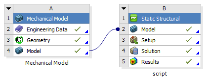
Could the inability to reference the name created at the contact be a result of our Workbench setup? We set up our model (connections and mesh) in one system and then connect this to other systems where we setup load case specific connections and loads. I've tried adding the commands at the connections in the first system (Mechanical Model), but these are not imported to the second system (script).
WB_setup_yenjc9.png


I thought the ID was specific to each contact. I simply went into the Solver Output and found the contact creation
Connection_gtvnbm.png


As I see it from the command inserted at the connection, the real constant should equal the contact ID
Connection_command_grbqzj.png

Hence, it seems to me, that BB_1_1 = cid (= 159).

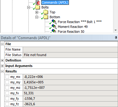
Command_result_BB_xnhvos.png
              
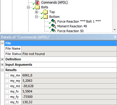
Command_results_159_xhfwzq.png

Left image is results from script using esel, s, type,, BB_1_1.                     Right image is results from script using esel, s, type,, 159.

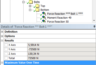
Force_results_rfe0of.png
              
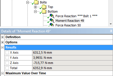
Moment_results_olwgvz.png

Left image is force results from probe at Contact (Underlying Element).        Right image is moment results from probe at Contact (Underlying Element).

The file status for the script says File not found. What does this mean? I haven't been able to find anything searching online and in the manual.
Could there be some setting that I have not set properly in Mechanical to make it possible to use the script at the contact?
 
Hi Dixib,

The *GET forces and moments from my script matches well with WB probe so the general framework should be correct.


OP said:
Could the inability to reference the name created at the contact be a result of our Workbench setup?
The named selections should go through.

OP said:
Could there be some setting that I have not...
It's hard to troubleshoot your model from afar. Try starting with a simple model, make sure that works and build up complexity to troubleshoot.

OP said:
... in the underlying elements, I asked for a way to do this...
The script would depend on the contact settings used. Here's a slight modification of the original script that does that. The results are the same for my model:
Code:
/post1
set, last
esel, s, type,, mycid   ! contact elements
nsle
esln                    ! all elements (underlying, contact, target etc)

! Selects solid elements at one side of contact
! usually lowest element number *big ASSUMPTION HERE*
enum1 = elnext(0)       
*get, etnum1, elem, enum1, attr, type 
esel,r,type,,etnum1     ! selects underlying elements
nsle,r                  ! selects underlying nodes

nwpave, all
cswpla, 101, 0
*get, xloc, cdsy, 101, loc, x
*get, yloc, cdsy, 101, loc, y
*get, zloc, cdsy, 101, loc, z

spoint,, xloc, yloc, zloc
!fsum,,cont
fsum
*get, my_fx, fsum, 0, item, fx
*get, my_fy, fsum, 0, item, fy
*get, my_fz, fsum, 0, item, fz
*get, my_mx, fsum, 0, item, mx
*get, my_my, fsum, 0, item, my
*get, my_mz, fsum, 0, item, mz


Kind regards,
Jason
 
Status
Not open for further replies.

Part and Inventory Search

Sponsor